Shielded treatment environment for brachytherapy source

a radiation shielding and treatment environment technology, applied in the field of radiation shielding systems, can solve the problems of large floor space requirements, relatively high cost, and none of these are arguably suitable for the very high radiation exposure rate and high gamma ray energies encountered in high dose rate brachytherapy, so as to reduce radiation exposure of staff, reduce exposure to primary radiation, and reduce the effect of secondary radiation

Inactive Publication Date: 2007-10-02
IMPLANT SCI
View PDF18 Cites 17 Cited by
  • Summary
  • Abstract
  • Description
  • Claims
  • Application Information

AI Technical Summary

Benefits of technology

[0036]The system described herein is designed to reduce the radiation exposure of staff in the treatment room.
[0037]The system described herein is also designed to substantially reduce exposure to primary radiation around a treatment platform and thereby permitting physicians and therapists to observe the patient without being exposed to excessive amounts of radiation.
[0038]The system

Problems solved by technology

These rooms may require large amounts of floor space to house the patient, the treatment device and the treatment personnel who prepare the patient for treatment.
Because of the large size of these rooms, the rooms may require an enormous amount of shielding material, which results in a relatively high cost.
The large number of prospective patients for this treatment protocol could tax the availability of existing treatment facilities, and could require the construction of new dedicated shielded treatment rooms.
This could have the adversely effect of the comfort of the patient, by making the patient feel “closed in”, creating apprehension much like that one experiences during a closed magnetic resonance imaging examination.
Localized shielding environments have been used for other diagnostic and therapeutic applicati

Method used


Image

  • Shielded treatment environment for brachytherapy source
  • Shielded treatment environment for brachytherapy source
  • Shielded treatment environment for brachytherapy source

Examples


Embodiment Construction

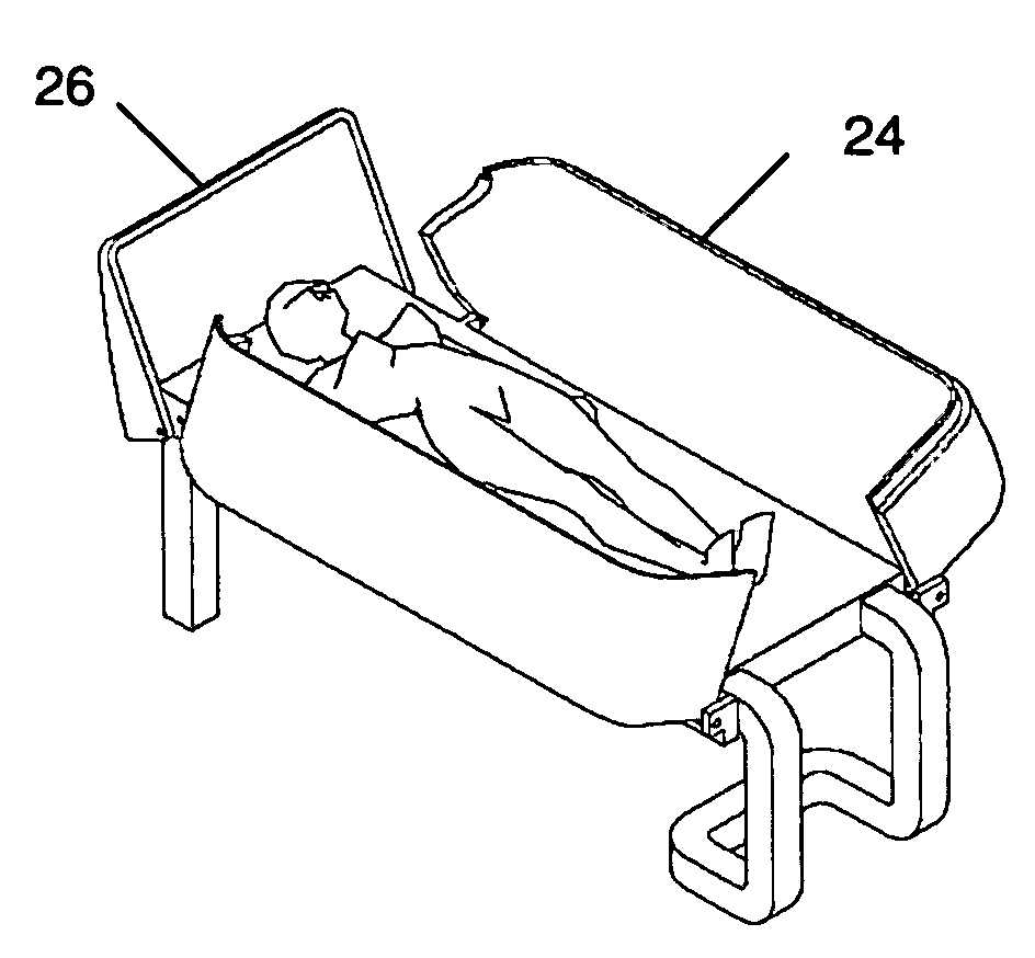
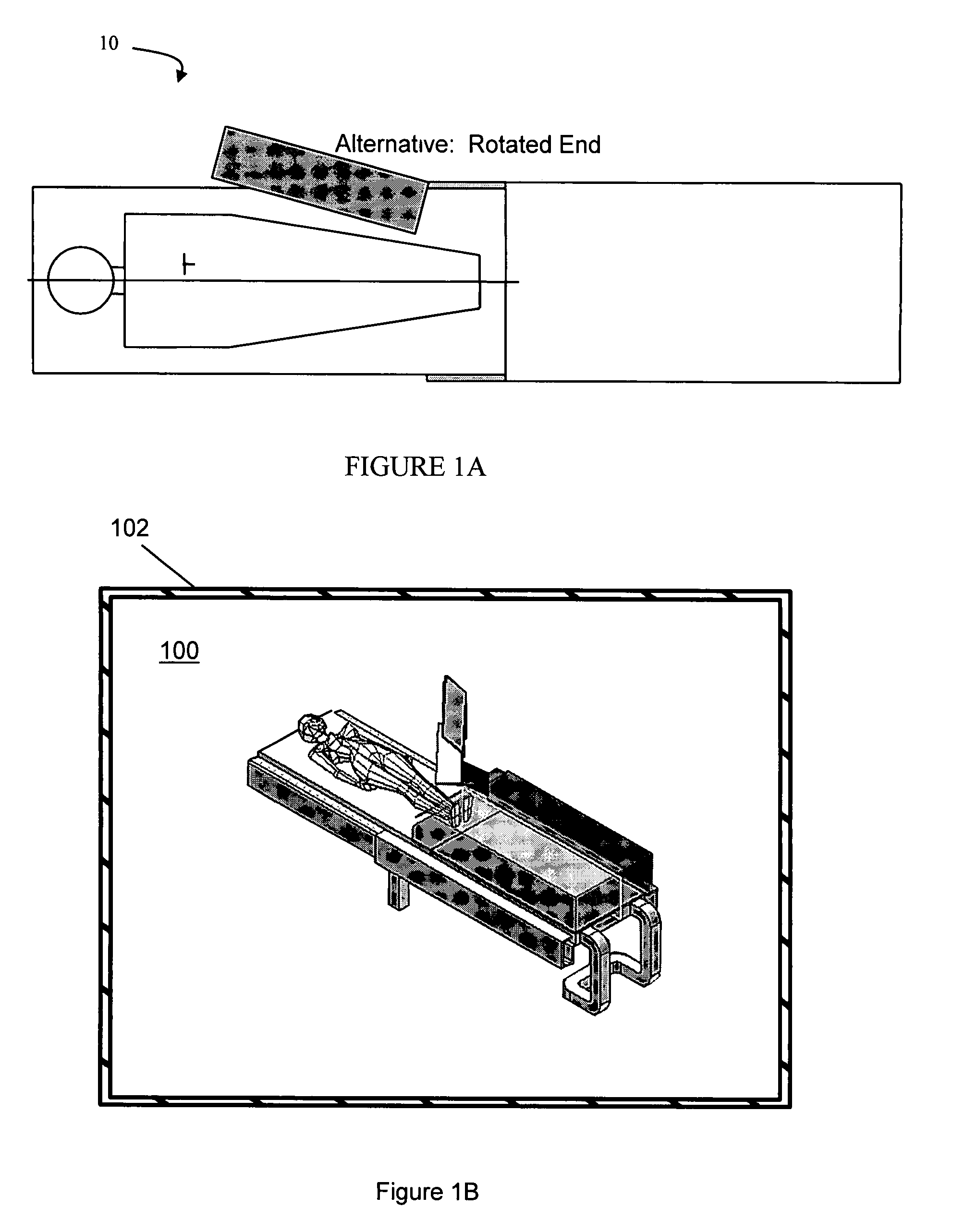
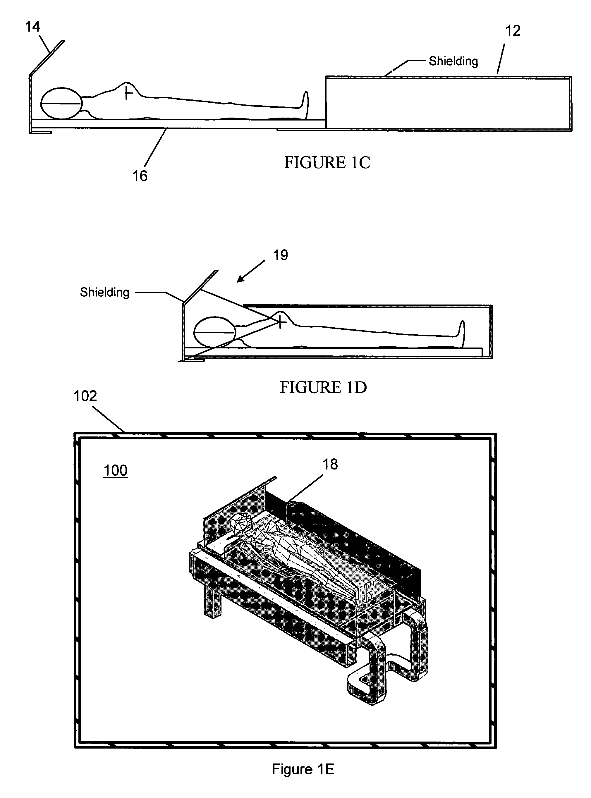
[0048]FIGS. 1A-1E illustrate a radiation protection system 10 that covers a patient on a treatment platform in the form of a table designed for breast brachytherapy procedures in which the patient is in a supine position. In one embodiment, the radiation protection system 10 includes a shielded tunnel 12. Each side of the shielded tunnel 12 is provided with sufficient lead or other shielding material to provide sufficient protection to adjacent personnel. A shielded cap 14 at the head, which may be motorized, pivots into place once the patient is positioned, providing shielding in the superior direction (FIGS. 1A, 1B). In an alternative embodiment, shielded cap 14 may be disposed at the head of table 15 (FIG. 1C). Cap 14 may be fixed in place or may be hingely attached to table 16, so that it may be positioned after the patient is in position. The elements 12, 14 may provide shielding for the primary radiation in the directions from which health care providers or others may approach...


PUM


Abstract

A radiation protection system for shielding medical personnel from a gamma ray source being used to provide brachytherapy to a patient is provided by disposing shielding material between the source of radiation and locations outside the radiation protection system in such a manner as to provide shielding for the primary radiation in directions from which radiation from the source may emerge, while providing the patient an open viewing area with a large field of view for the patient to view the locations outside the radiation protection system. The described system reduces the radiation exposure of staff in the treatment room, thereby permitting physicians and therapists to observe the patient without being exposed to excessive amounts of radiation. The opening in the radiation protection system around the head of the patient provides the ability for the patient to see his surroundings and to eliminate the anxiety resulting from the feeling of being closed in.

Description

BACKGROUND OF THE INVENTION[0001]1. Technical Field[0002]This system described herein relates generally to radiation protection systems and, more particularly, to radiation shielding systems integrated into procedural environments for use in the course of therapeutic procedures, for example, to radiation shielding systems integrated into procedural environments for use in the course of the performance of brachytherapy procedures as well as methods for the use of such systems.[0003]2. Description of Related Art[0004]Various techniques have been developed to treat tumors in the body. In general, the use of radiation to reduce or eliminate malignancy has been known for many years.[0005]Brachytherapy is a method of radiation treatment of cancerous tissue in which the radiation source is placed in or near the cancerous tissue. Brachytherapy treatment permits administration of higher radiation dose to the tumor with better sparing of surrounding normal healthy tissues.[0006]Temporary brac...

Claims


Application Information

Patent Timeline
IPC IPC(8): G21F3/00
CPCA61N5/1007A61N2005/1094
Inventor MUNRO, III, JOHN J.
Owner IMPLANT SCI
Why Eureka
Try Eureka