Imaging lens array

a technology of imaging lens array and lens array, which is applied in the field of small-type imaging lens array, can solve the problems of unstable whole system, unstable type of lens arrangement, and difficult adhesion work for adhesion of them together, so as to improve precision, minimize errors, and stable performance

Active Publication Date: 2007-10-02
LARGAN PRECISION
View PDF2 Cites 49 Cited by
  • Summary
  • Abstract
  • Description
  • Claims
  • Application Information

AI Technical Summary

Benefits of technology

[0009]The primary objective of the present invention is to provide an imaging lens array that has stable performance and improved precision, wherein a first lens is a positive meniscus lens with a convex surface facing the object side; a second lens is a negative meniscus lens with a convex surface facing the object side; a third lens is a positive meniscus lens with a convex surface facing image side; and fourth lens is a positive meniscus lens with a convex surface facing the object side. When the second, third and fourth lenses are double-sided aspherical lenses, the respective lenses of the present invention can be ensured to have an appropriate power, it also can minimize error, and improve the image quality.
[0010]The secondary objective of the present invention is to provide an imaging lens array consisted of four lenses, wherein the second, third and fourth lenses are made of plastic material, so that they can be produced more easily and the production cost can be reduced effectively.
[0011]The third objective of the present invention is to provide an imaging lens array, wherein all the numerical values of the respective lenses are represented in some unambiguous equations, so it can ensure the performance of the respective lenses.

Problems solved by technology

However, this type of lens arrangement still has some technical defects as follows:
First, a first lens of the existing lens arrays is a double convex lens, while a second lens thereof is a double concave lens, and the first and second lenses will have an excessive ability, causing instability to the whole system.
Second, since the first and second lenses are double convex lens and double concave lens, respectively, and they are made of glass and are adhered to each other, plus the outer diameters of the first and second lenses are very small (small lens), the adhering work for adhering them together will not be easy.
And as a result, the production cost for making this lens array will be high and the yield rate will be relative low.

Method used


Image

  • Imaging lens array
  • Imaging lens array
  • Imaging lens array

Examples


Embodiment Construction

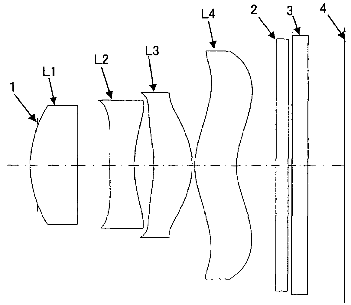
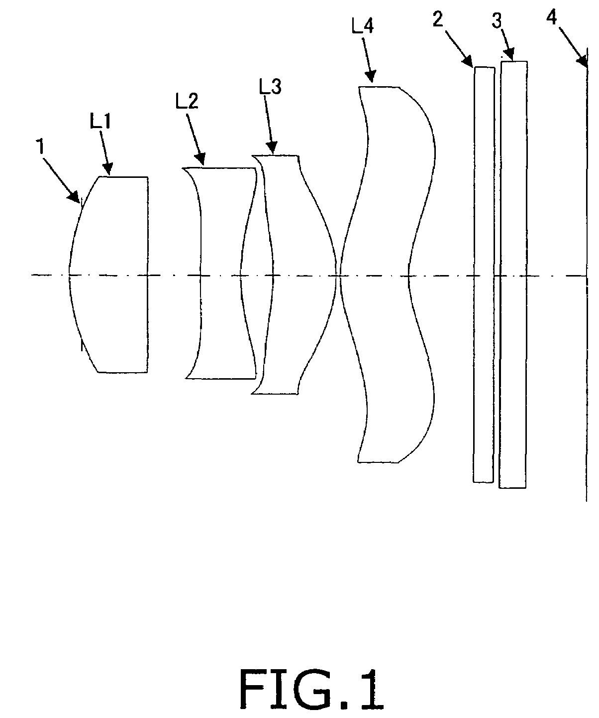
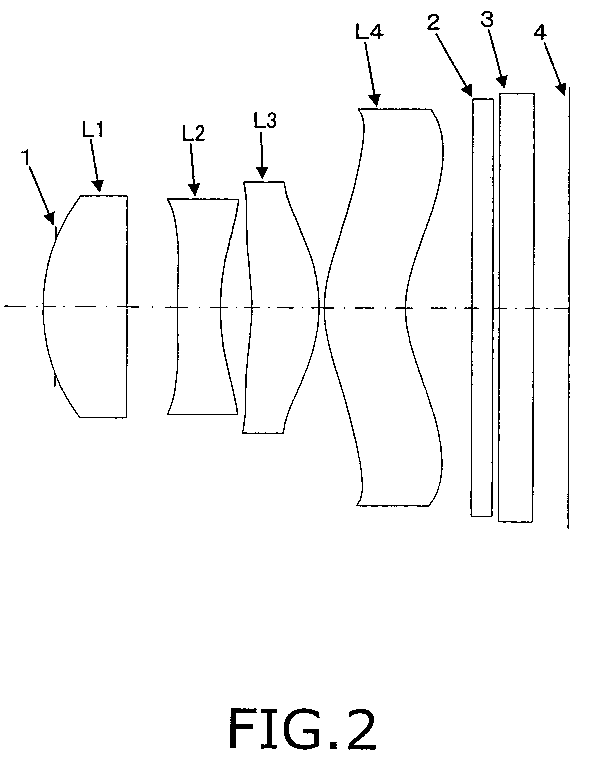
[0038]Referring to FIGS. 1-9, which show an imaging lens array in accordance with the present invention and comprises, from the object side, an aperture 1, a first lens L1, a second lens L2, a third lens L3, a fourth lens L4, two pieces of flat glass 2, 3 and image-forming plane 4.

[0039]The first lens L1 is a positive meniscus lens (or plano-convex lens) with a convex surface facing the object side.

[0040]The second lens L2 is a negative meniscus type double-sided aspherical lens with a convex surface facing the object side.

[0041]The third lens L3 is a positive meniscus type double-sided aspherical lens with a convex surface facing the image side.

[0042]The fourth lens L4 is a positive meniscus type double-sided aspherical lens with a convex surface facing the object side.

[0043]The flat glass 2 serves as an infrared filter, and the other flat glass 3 is parallel to the flat glass 2 and serves to protect the solid imaging device. Furthermore, on the image-forming plane 4 are provided C...


PUM


Abstract

An imaging lens array that has stable performance and improved precision, wherein a first lens is a positive meniscus lens with a convex surface facing the object side; a second lens is a negative meniscus lens with a convex surface facing the object side; a third lens is a positive meniscus lens with a convex surface facing image side; and fourth lens is a positive meniscus lens with a convex surface facing the object side. When the second, third and fourth lenses are double-sided aspherical lenses, the respective lenses of the present invention can be ensured to have an appropriate power, it also can minimize error, and improve the image quality.

Description

BACKGROUND OF THE INVENTION[0001]1. Field of the Invention[0002]The present invention relates to a small type imaging lens array, and more particularly to an imaging lens array consisted of four lenses that are arranged at predetermined intervals.[0003]2. Description of the Prior Arts[0004]Since the image pick up lens has an increasingly wide range of application, plus the consumer electronic industrial is growing fast, the small image pick-up lens is accordingly found in great demand in different fields, particularly in photographic cell phone, digital camera, or auto's detection system for parking or other purposes.[0005]A photosensitive element for a digital fixed focus lens array is merely of charge coupled device (CCD) type or CMOS type Complementary Metal Oxide Semiconductor, and its light sensitivity will be reduced sharply with the increase of exit angle of the lens. Therefore, the digital fixed focus lens array usually comprises 3-4 pieces of lens. However, this type of len...

Claims


Application Information

Patent Timeline
Patent Type & Authority Patents(United States)
IPC IPC(8): G02B13/08G02B9/34
CPCG02B9/34G02B13/18G02B13/004
Inventor NODA, SAYURI
Owner LARGAN PRECISION
Why Eureka
Try Eureka