

Method for power-saving operation of communication terminals in a communication system in especially in a wireless communication systems
- Summary
- Abstract
- Description
- Claims
- Application Information
AI Technical Summary
Benefits of technology
Problems solved by technology
Method used
Image

Examples
Embodiment Construction
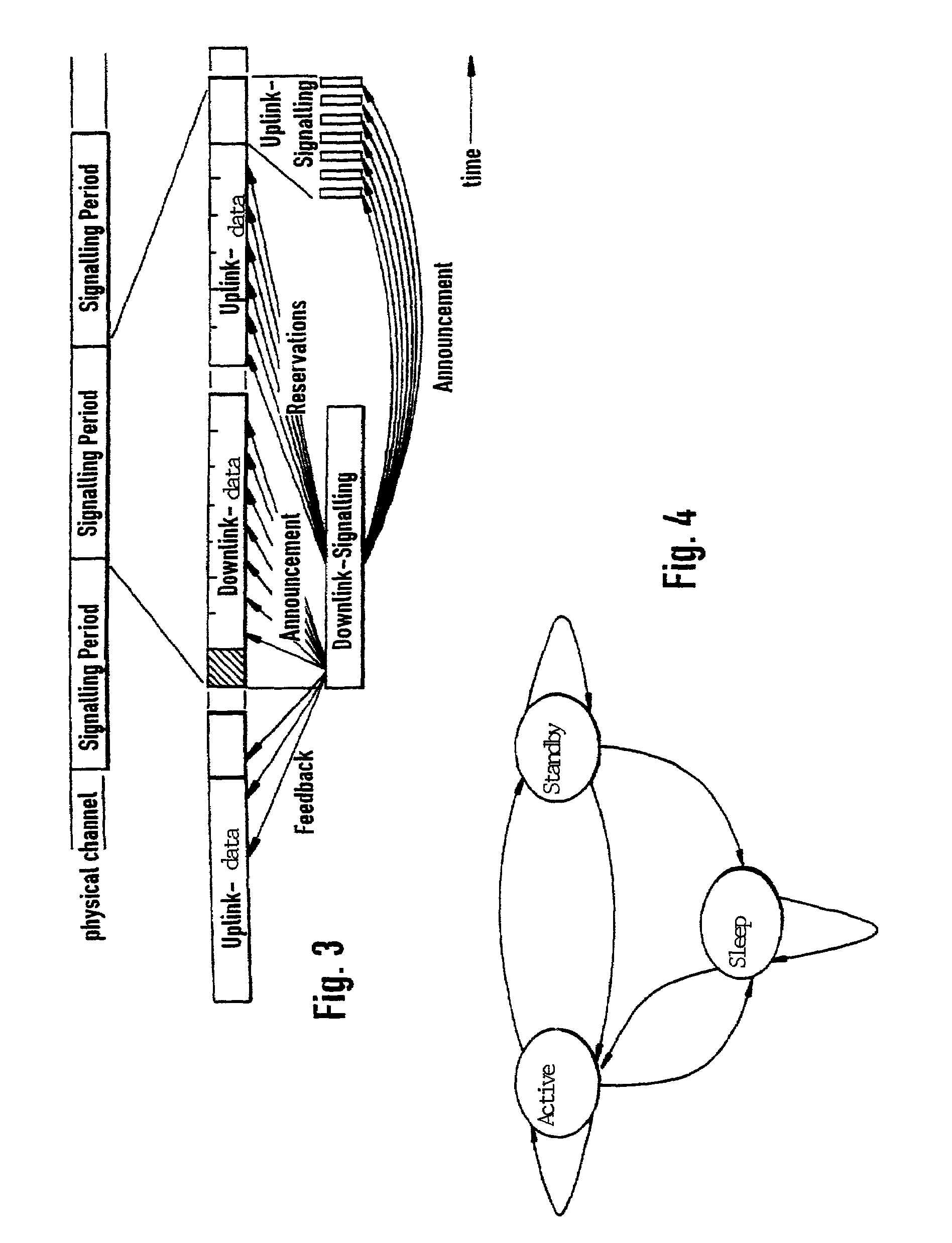
[0041]Before discussing the actual method according to the present invention, first the transmission frame shown in FIG. 3, on which the present invention is based, will be described. The basic principle of the DSA (Dynamic Slot Assignment) protocol is described in detail in German Patent Application No. P 197 26 120.5. The method described here can be used for FDD (Frequency Division Duplex) systems as well as TDD (Time Division Duplex) systems. It is assumed below without restricting the general scope of the present invention that transmission is by the TDD (Time Division Duplex) system. The physical channel is divided into time slots, each holding one data burst. Such a data burst contains an ATM cell including the required overhead for a training sequence, synchronization, forward error correction FEC, and protection times. In the downlink signaling burst, the master station allocates to each terminal a certain transmission capacity in the form of time slots for a specific inter...
PUM
 Abstract
Description
Claims
Application Information