Cryogenic storage system

a cryogenic storage and storage temperature technology, applied in the direction of domestic cooling apparatus, container discharge methods, lighting and heating apparatus, etc., can solve the problems of requiring the manipulation of storage temperature and the inability to bank large tissue masses, and achieve the effect of minimizing net heat flow, simple movement, and modest power requirements

Active Publication Date: 2007-10-09
21ST CENTURY MEDICINE
View PDF7 Cites 64 Cited by
  • Summary
  • Abstract
  • Description
  • Claims
  • Application Information

AI Technical Summary

Benefits of technology

[0051]Thermally conductive elements 50 (e.g., as depicted in FIGS. 5–8) can be immersed in liquid cryogen and are useful for improving the temperature stability of systems that are dependent on cryogen levels. The platform 80 at the bottom of the Dewar (or other cold source) is also a conductive element and lifts the storage container out of the liquid cryogen and into the vapor space. The platform 80 remains at a temperature near the boiling temperature of LN2 regardless of the LN2 level. This improves the temperature stability of the vapor space above the LN2 between refills of LN2. Even in the absence of such conductive elements, a great advantage of the present invention is that the interior of storage containers is protected from temperature fluctuations in the vapor space that can accompany cryogen refills. Vertical stands 54 serve to provide a stable support for the platform and are also conductive elements.
[0052]FIG. 8 illustrates the principle that the environment surrounding the storage container 11 of the present invention can be of very non-uniform temperature. In the figure, the platform 80 in contact with the bottom of the container is at the boiling temperature of LN2 22, while the vapor in contact with the Dewar lid 62 is close to the ambient temperature outside the Dewar. Large environmental temperature non-uniformity is permissible provided that the thermally conductive container 12 and surrounding thermal insulation 19 are of sufficient thickness to satisfy temperature uniformity requirements within the container. The container also need not operate at a target temperature near the mean temperature of the environment. In the example shown in the figure, the insulation at the bottom of the container 82 is thinner than insulation at the top 84, thereby permitting the interior of the container to be maintained at a temperature that is closer to the temperature at the bottom of the Dewar than at the top. Other designs for fine tuning the insulation balance between the container top and bottom are also possible. For example, conductive braids penetrating the bottom insulation could be raised or lowered into the LN2 to adjust the equilibrium temperature of the container interior.
[0053]In the embodiments discussed above, a cryogenic Dewar holding a boiling cryogen is used as a cold source for the invention. But many other environments and configurations can serve as cold sources for the invention. These include, but are not limited to, vessels insulated with perlite, aerogel or foam at either ambient or soft-vacuum pressure. Cold can be maintained within the vessels by either cryogens, cold fingers, thermoelectric piles, or by placing the vessels in a mechanical refrigerator or freezer. The storage containers of the invention can be surrounded by cold vapor, cold liquids, or cold solids, or any combination thereof sufficient to generate positive or zero heat flow from the container interior. Surrounding vapor or fluids can be either static or moving.
[0054]FIG. 9 illustrates that a vessel holding the storage container(s) 11 and cold source is not essential for the invention to work. In the figure a storage container 11 merely rests against a cold plate 90. Provided that the magnitude of the heat flow to the cold plate 90 equals or exceeds the flow of heat from the warmer temperature chamber 10, the target temperature of the temperature chamber 10 can be maintained. Continuous or intermittent pouring of cold cryogen over a container exterior is another example of a cold source or heat sink that does not require a surrounding vessel. For example, liquid nitrogen might be intermittently poured over a container during transport operations through air outside of the cold source.
[0055]While many applications of the invention involve cryogenic temperatures, the invention can also operate in other temperature ranges. For example, transplantable tissues and organs that are not cryopreserved are typically transported in ice water at 0° C. If temperatures higher than 0° C. were optimal for short-term preservation of material, the invention could be used to transport material at a stable higher temperature using melting water ice as the cold source or heat sink.
[0056]The present invention offers the advantage of a storage container that can be placed into virtually any environment where the surrounding temperature (or sufficient portion thereof) is below the target temperature for the temperature chamber, and the desired target temperature can still be maintained within the container interior. For example, if the storage containers are being maintained in a larger storage container, and the large container fails, the storage containers can be moved into any other sufficiently cold environment and will function normally. If storage containers must be moved long distances, they can be easily moved inside of simple cryogen-bearing transport Dewars or boxes. As long as power is available for the control electronics (e.g., by use of batteries), the container interiors can be maintained at a constant and uniform temperature even if the surrounding environment has a very non-uniform and poorly-controlled temperature.

Problems solved by technology

Stable storage for long periods of time typically requires cold temperatures.
However vitrification of large objects involves problems that don't exist for small (microliter) objects (Fahy, et al., “Physical problems with the vitrification of large biological systems,”Cryobiology 27, pp.
A major problem in vitrification is fracturing.
These systems are not suitable for banking of large tissue masses where fracturing is a concern.
Furthermore, annealing protocols require the storage temperature to be manipulated over potentially long periods of time.

Method used


Image

  • Cryogenic storage system
  • Cryogenic storage system
  • Cryogenic storage system

Examples


example 1

Manufacture of a Storage Container Device

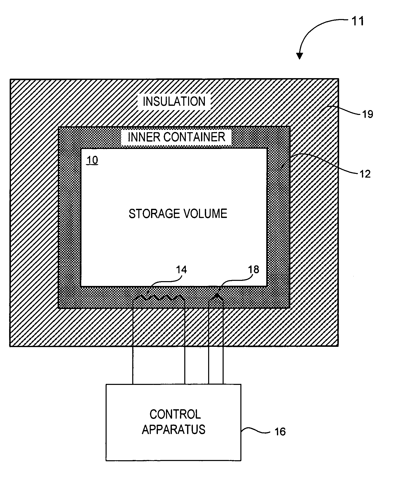
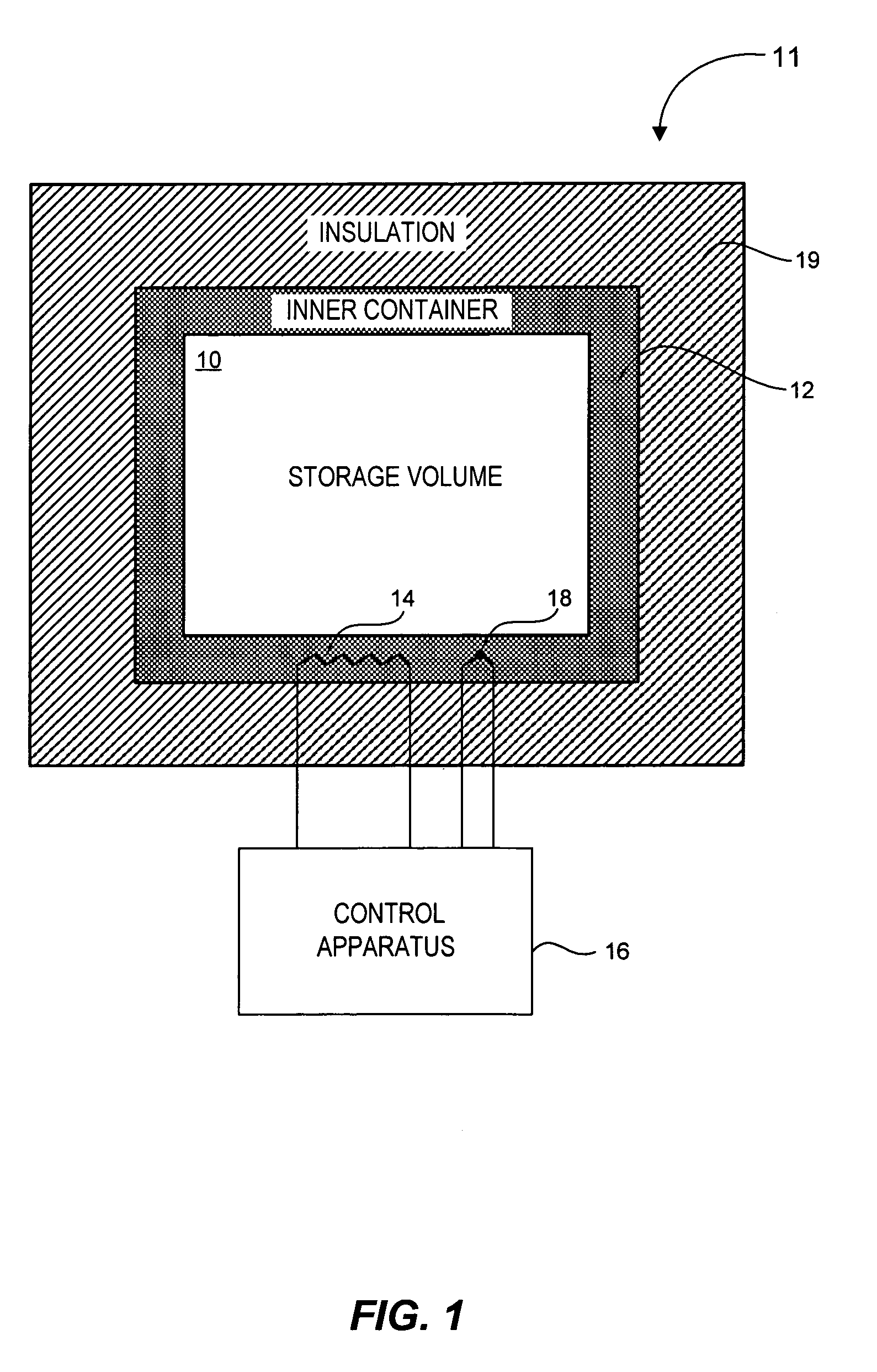
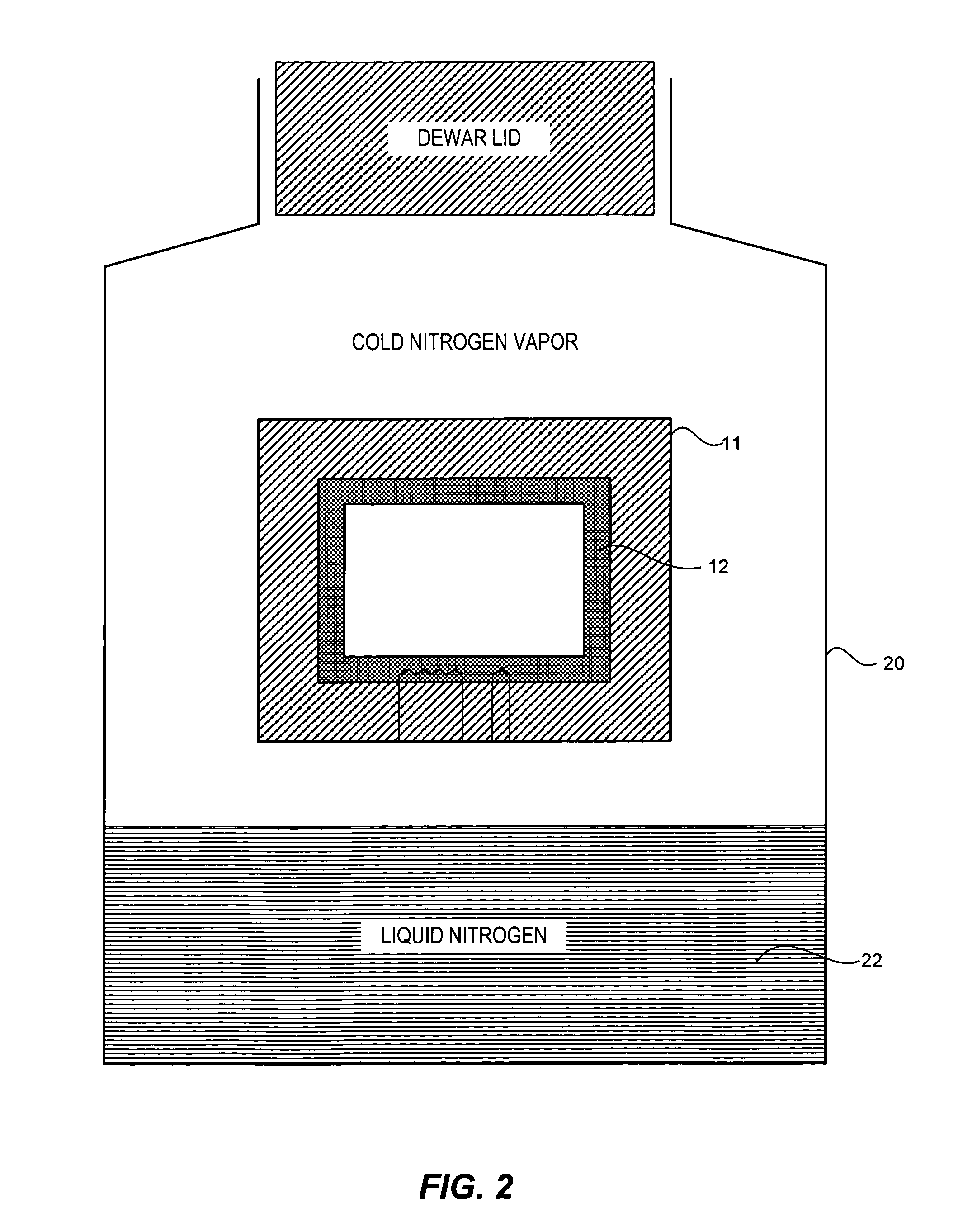
[0062]A cylindrical aluminum container of 30 cm diameter, 30 cm height, and 3 mm thickness is obtained. The thermally conductive aluminum container has a temperature chamber within and is surrounded on all sides by a foam insulation of 5 cm thickness. The insulation has a thermal conductivity of 0.03 W / mK. The top portion of the container is formed as a lid to allow access to the temperature chamber inside. The container is placed inside a Dewar (as shown in FIG. 2) such that the bottom of the container rests on or near the surface of LN2 inside the Dewar. The bottom of the container is at a temperature of approximately −196° C. The temperature of the vapor in the Dewar is stratified such that the top of the container is at a temperature of −120° C. The target temperature for the temperature chamber is −150° C.

[0063]In another embodiment a Dewar similar to that shown in FIG. 11 is obtained having a diameter of 1 meter and an inner wall of 1 m...

example 2

Thermal Flow

[0064]The external surface area of the container of Example 1 is about 0.75 square meters. If the bottom half of this surface area is at −196° C., and the temperature chamber in the interior is at −150° C., the heat flow out of the container will be 11 watts, and the LN2 consumption will be about 5 liters per day or less. Similarly, if the top half of the container is at −120° C., the heat flow into this half will be approximately 7 watts. The difference between the 7 watt inflow and 11 watt outflow is made up by 5 watts of electric heat applied to the bottom of the thermally conductive container.

[0065]Seven watts travels from the top to the bottom of the aluminum thermally conductive container. The wall of the thermally conductive container has a cross sectional area of 0.003 square meters, and aluminum has a thermal conductivity of approximately 240 W / mK. The top-to-bottom temperature difference of the thermally conductive container is therefore only 3° C. despite the ...

example 3

Heat Sources and Heat Distribution

[0073]FIG. 13 depicts an example that is analogous to the setup described in Example 1, except that three large storage containers are placed in the Dewar instead of 25 smaller ones. Each storage container device is 2 meters long and has a temperature chamber defined by a 3 mm thick aluminum thermally conductive container. The containers have about 5 cm thick conventional foam insulation on all sides. The internal temperature is 135° C., and thermal contact with the central cold elements 1100 is arranged so that there is a 4 watt heat flow out of each storage container. System performance is 17 liters per day LN2 consumption.

[0074]In some embodiments multiple internal temperature sensing and heating points are used. In one embodiment a single resistive heater encircles the inner diameter of a container and supplies the requisite heating with only a 3° C. temperature variation within the container. In one embodiment independently controlled heaters a...


PUM


Abstract

The present invention provides devices and methods for the cryogenic storage of biological material. Devices of the invention are useful for storing material at a cryogenic temperature. The devices include a temperature chamber defined by a thermally-conductive container and at least one layer of thermal insulation surrounding the thermally-conductive container. Some embodiments utilize one or more heat sources thermally connected to the thermally conductive container. Other embodiments are arranged so that no net flow of heat occurs from the temperature chamber when the temperature chamber is at a set target temperature. Also provided are methods of using the devices.

Description

[0001]This application claims the benefit of U.S. application Ser. No. 60 / 478,674, filed Jun. 12, 2003, which is hereby incorporated by reference in its entirety, including all Figures, Table, and Claims.FIELD OF THE INVENTION[0002]The present invention relates to the field of cryogenic storage systems.BACKGROUND OF THE INVENTION[0003]The following discussion of the background of the invention is merely provided to aid the reader in understanding the invention and is not admitted to describe or constitute prior art to the present invention.[0004]Stable storage for long periods of time typically requires cold temperatures. This is especially true for biological tissue. Water located between ice crystals contains concentrated solutes, and therefore remains a viscous fluid until the glass transition temperature is reached. At the glass transition temperature a crystal-free immobilized liquid state known as a “glass” is formed. This typically occurs between −80° C. and −130° C. Below th...

Claims


Application Information

Patent Timeline
Patent Type & Authority Patents(United States)
IPC IPC(8): F25D3/08A01N1/02F17C5/00F17C13/00F25B21/00
CPCA01N1/02A01N1/0263A01N1/0268F17C2203/0304F17C2203/0617F17C2203/0629F17C2203/0646F17C2203/0648F17C2205/0149F17C2227/0337F17C2250/0439F17C2203/0636A01N1/0257F25D3/105
Inventor WOWK, BRIANIAROCCI, MICHAEL
Owner 21ST CENTURY MEDICINE
Why Eureka
Try Eureka