Check patentability & draft patents in minutes with Patsnap Eureka AI!

Obstacle detection system

a detection system and obstacle technology, applied in the direction of instruments, specific gravity measurement, reradiation, etc., can solve the problems of general versatility, hardware including filter circuits lack general versatility, and stringent specification of microphones become unnecessary, and achieve the effect of high general versatility

Active Publication Date: 2007-10-09
DENSO CORP
View PDF16 Cites 9 Cited by
  • Summary
  • Abstract
  • Description
  • Claims
  • Application Information

AI Technical Summary

Benefits of technology

The present invention provides an obstacle detection system that can detect obstacles accurately and easily. The system uses ultrasonic sensors that can be adjusted to different frequencies, making it easy to set up and use with different microphones. This results in a more versatile and flexible system that can detect obstacles in different situations.

Problems solved by technology

Therefore, a stringent specification to the microphone becomes unnecessary.
The hardware including the filter circuit therefore lacks general versatility.

Method used


Image

  • Obstacle detection system
  • Obstacle detection system
  • Obstacle detection system

Examples


Embodiment Construction

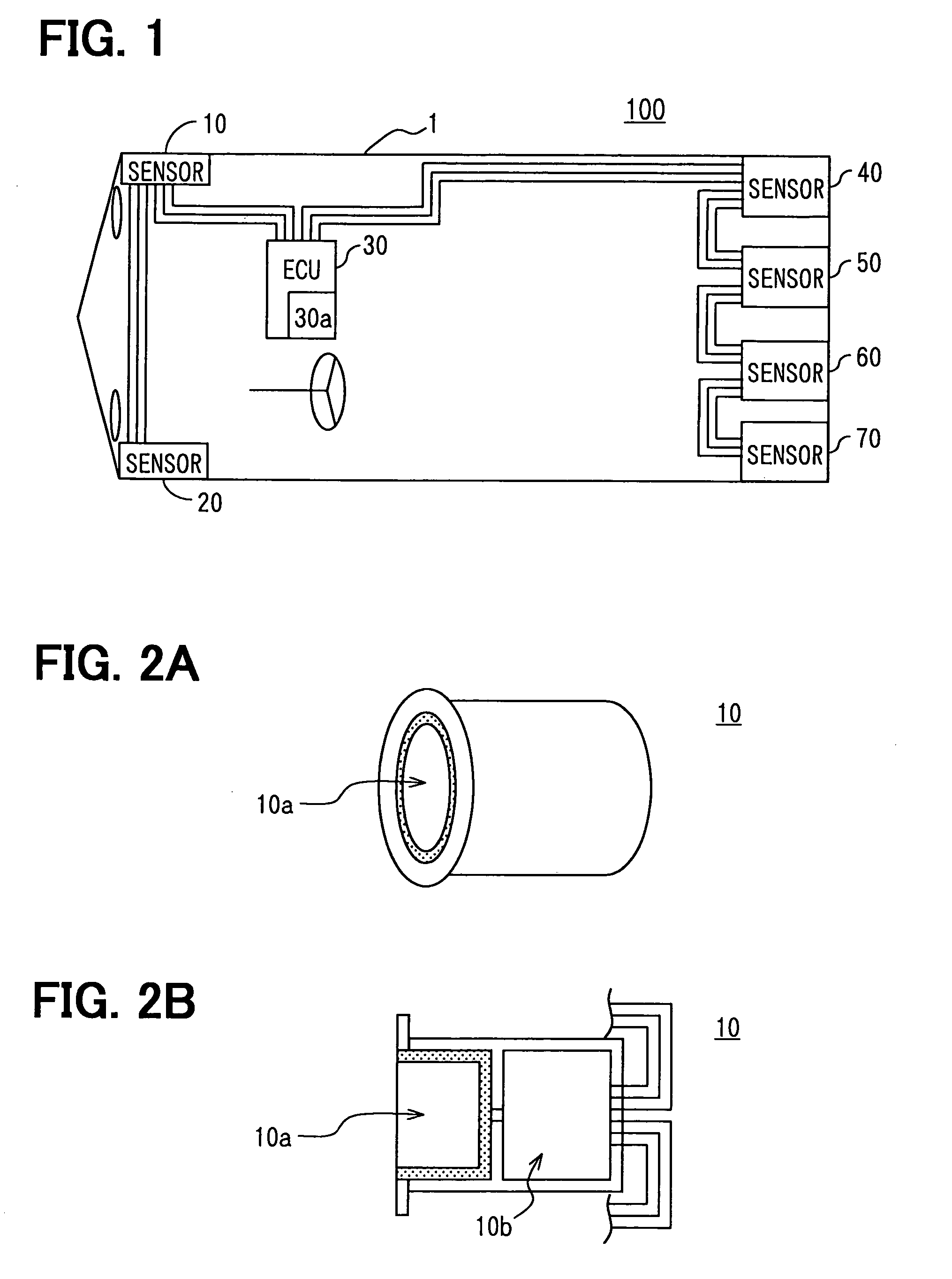
[0019]Referring to FIG. 1, an obstacle detection system 100 for a vehicle 1 has sensors 10 and 20 arranged at right and left corners on a front bumper part of a vehicle 1; sensors 40 to 70 arranged at right and left corners and a center part on a rear bumper part of the vehicle; and an electronic control unit (EMU) 30. The sensors 10 to 70 are bus-connected to the EMU 30 through serial communication lines. The sensors 10 to 70 transmit ultrasonic waves in the front direction and in the rear direction of the vehicle 1 and receive reflected waves reflected by an obstacle (not shown).

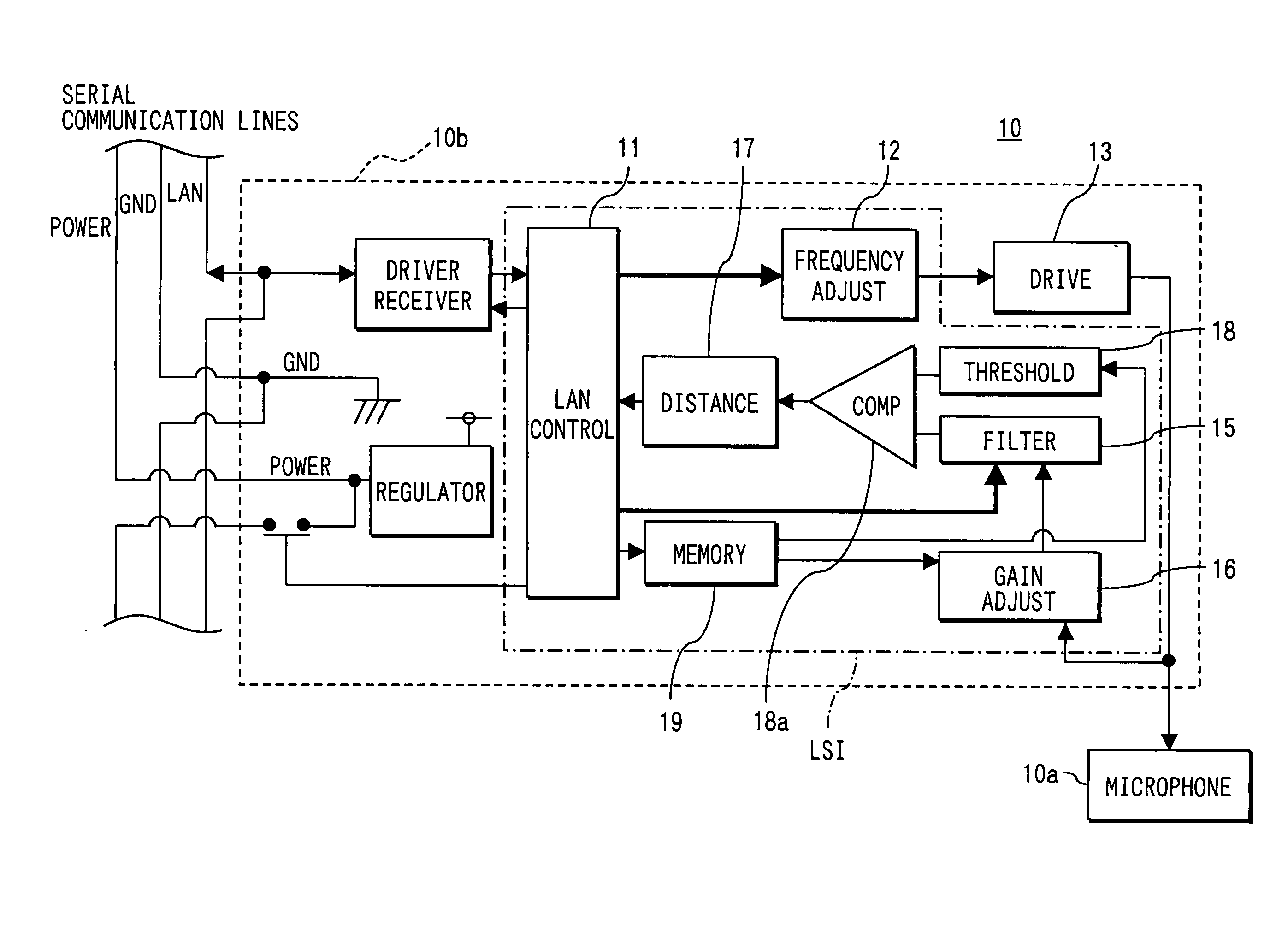
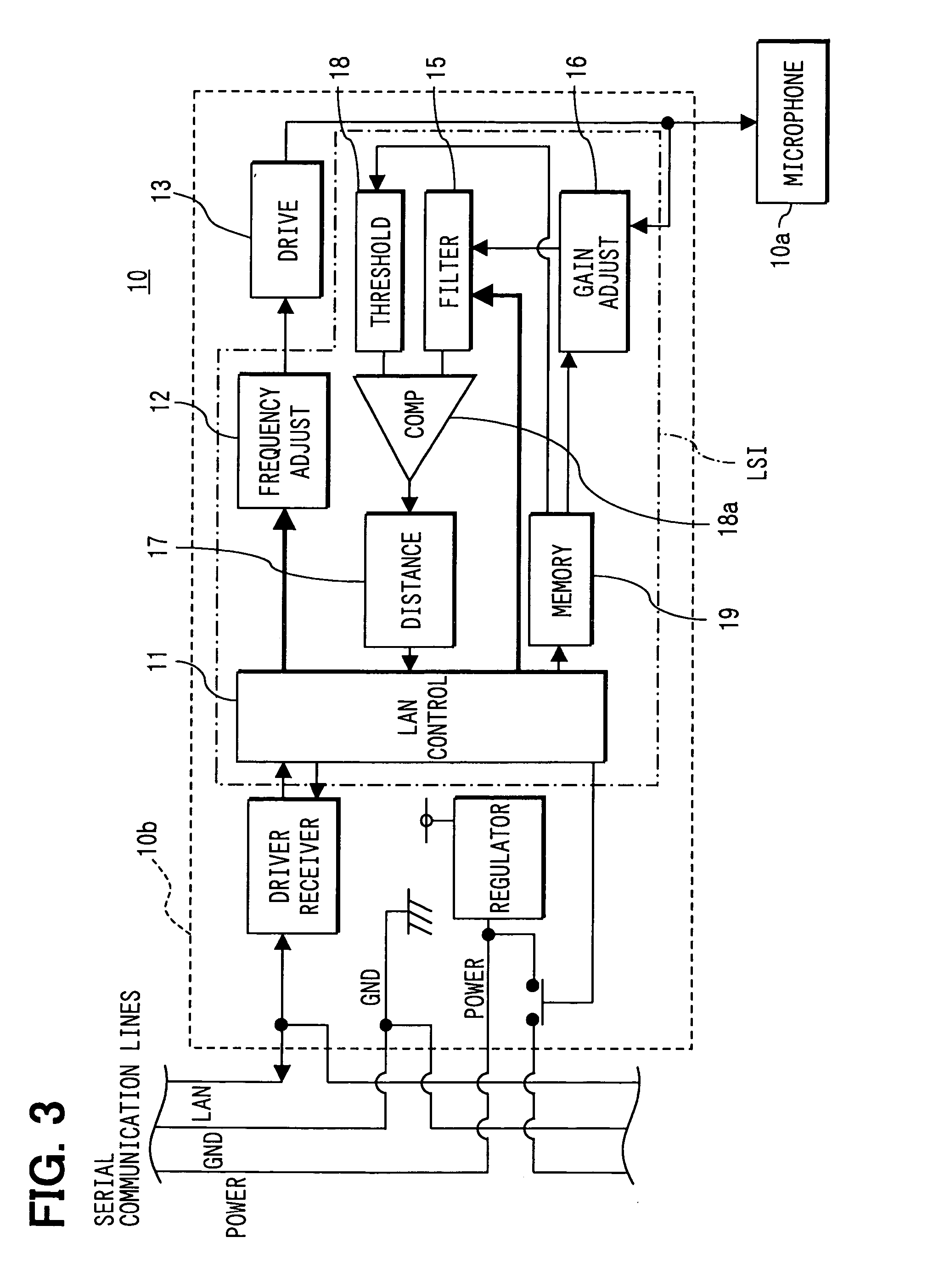
[0020]The sensor 10 may be constructed with a microphone 10a and an electronic circuit unit 10b as shown in FIGS. 2A and 2B. Other sensors 20 to 70 may be constructed similarly to the sensor 10.

[0021]The EMU 30 has a nonvolatile memory 30a. This nonvolatile memory stores sensor IDS corresponding to the sensors 10 to 70 and the correspondence table shown in FIG. 6.

[0022]The EMU 30 performs processing of tra...


PUM

PropertyMeasurementUnit
resonance frequencyaaaaaaaaaa

Abstract

A plurality of ultrasonic sensors is provided in both front and rear bumpers of a vehicle to detect obstacles around the vehicle. Each sensor sets up a transmission frequency of an ultrasonic pulse signal that should be set up in a frequency adjustment circuit and a center frequency in filter processing in a filter circuit in response to a frequency setting frame transmitted from an EMU. The EMU stores a combination of the transmission frequency and the center frequency for each ultrasonic sensor.

Description

CROSS REFERENCE TO RELATED APPLICATION[0001]This application is based on and incorporates herein by reference Japanese Patent Applications No. 2004-211752 filed on Jul. 20, 2004 and No. 2005-124065 filed on Apr. 21, 2005.FIELD OF THE INVENTION[0002]The present invention relates to an obstacle detection system for vehicles.BACKGROUND OF THE INVENTION[0003]Conventionally, an obstacle detection system that smoothes out dispersion in the oscillation frequency of a microphone used for an ultrasonic sensor is proposed in, for example, US2003 / 0034883 A1 (JP 3521892 B2). In this obstacle detection system, first a microphone is assembled in a sensor circuit board, and then an obstacle for a test is disposed against the microphone. Subsequently, the obstacle detection system transmits an ultrasonic wave to this obstacle, finds an oscillation frequency of the ultrasonic wave that has a highest peak voltage of its reflected wave, and stores the oscillation frequency in a nonvolatile memory.[000...

Claims


Application Information

Patent Timeline
Patent Type & Authority Patents(United States)
IPC IPC(8): G01N29/00B62D1/00G01S15/931
CPCG01S7/52004G01S7/523G01S15/931G01S7/521G01S7/003G01S2015/938
Inventor SATO, YOSHIHISATAKEICHI, MASAKAZUKANI, HIROYUKI
Owner DENSO CORP
Features
  • R&D
  • Intellectual Property
  • Life Sciences
  • Materials
  • Tech Scout
  • Unparalleled Data Quality
  • Higher Quality Content
  • 60% Fewer Hallucinations
Learn More