Device for separating multi-phase fluids

a technology of multi-phase fluids and separators, which is applied in the direction of liquid separation, fluid removal, earthwork drilling and mining, etc., can solve the problems of large separation equipment, large separation equipment, and large space requirements, and achieve the effect of reducing the volume of the separator and improving performan

Active Publication Date: 2007-10-09
DEN NORSKE STATS OLJESELSKAP AS
View PDF13 Cites 35 Cited by
  • Summary
  • Abstract
  • Description
  • Claims
  • Application Information

AI Technical Summary

Benefits of technology

[0008]By first partially separating the incoming fluid flow in the pipe separator before the further separation in the co

Problems solved by technology

However, depending on their capacity, such separat

Method used


Image

  • Device for separating multi-phase fluids
  • Device for separating multi-phase fluids

Examples


Embodiment Construction

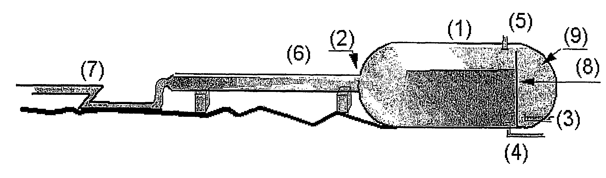
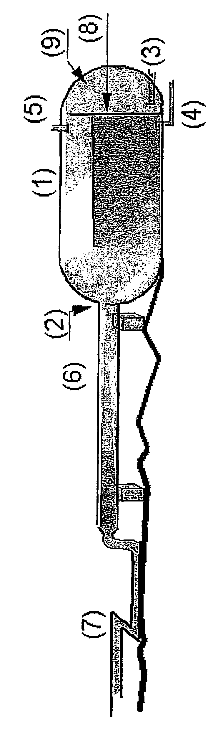
[0010]As the FIGURE shows, the present invention comprises a conventional gravitation separator 1, comprising a preferably cylindrical container with an inlet 2, a first outlet 3 for liquid with a higher gravity (for example water), a second outlet 4 for liquid with a lower gravity (for example oil) and a third outlet 5 for gas.

[0011]At the end of the container 1, a partition 8 is arranged expediently. It extends towards the upper end of the container and forms a threshold for liquid with a lower gravity (oil) to flow over to a chamber 9 on the right side of the container 1, where the second outlet 4 is arranged.

[0012]The special feature of the solution in accordance with the present invention is that a pipe separator 6 is connected to the inlet 2 for the conventional gravitation separator 1. The pipe separator 6 constitutes a continuation of a supply pipe 7 for the fluid to be separated and extends partially into the gravitation separator 1. The pipe separator 6 has a diameter that...


PUM


Abstract

A device in connection with a separator for separation of a multiphase fluid, including a preferably cylindrical container (1) with an inlet (2), a first outlet (3) for liquid with a higher gravity (for example water), a second outlet (4) for liquid with a lower gravity (for example oil) and a third outlet (5) for gas. A pipe separator (6) is connected to the inlet (2) of the container (1). The pipe separator (6) constitutes a continuation of a supply pipe (7) for supplying the fluid to be separated and extends partially into the container (1).

Description

BACKGROUND OF THE INVENTION[0001]1. Field of the Invention[0002]The present invention concerns a device in connection with a separator for separation of a multiphase fluid, comprising a preferably cylindrical container with an inlet, a first outlet for liquid with a higher gravity (for example water), a second outlet for liquid with a lower gravity (for example oil) and a third outlet for gas.[0003]2. Description of the Related Art[0004]The prior art contains gravitation separators of the above type for separation of fluids such as oil, water and gas which are used in a number of contexts in process plants on platforms and production ships or on the sea bed. However, depending on their capacity, such separators are large and heavy and require a lot of space.[0005]The prior art also contains a new type of separator, called a pipe separator, that has been developed by the applicant of the present application and is based on separation in a pipe by means of laminar flow of the separabl...

Claims


Application Information

Patent Timeline
IPC IPC(8): B01D17/025B01DB01D17/00B01D17/02E21B43/34
CPCB01D17/00B01D17/0208B01D17/0211B01D17/0214
Inventor SAGATUN, SVEIN IVARGRAMME, PER EIVIND
Owner DEN NORSKE STATS OLJESELSKAP AS
Why Eureka
Try Eureka