
"Zero" lash spherical differential assembly using spring washers

a technology of lash spherical differential and washer, which is applied in the direction of gearing details, gearing, transportation and packaging, etc., can solve the problems of low acceptance level of undesirable noise, no longer feasible design solution for washer adjacent to a side gear having a relatively large planar back surface area, etc., to achieve easy manufacturing, increase structural durability of driveline components, and tighten tolerances

Active Publication Date: 2007-10-09
AMERICAN AXLE & MFG
View PDF11 Cites 6 Cited by
  • Summary
  • Abstract
  • Description
  • Claims
  • Application Information

AI Technical Summary

Benefits of technology

[0003]Additionally, some presently produced differential assemblies include a housing having a spherical cavity in receipt of partially spherically shaped pinion gears and side gears. The use of spherically shaped components has allowed for increased structural durability of the driveline components and may be desirable. Furthermore, spherical shapes are easier to manufacture and allow tighter tolerances that provide for reduced lash between the gears. The use of spherically shaped side gears has substantially reduced the “back face” area on which a spring or other biasing device may be positioned to bias the side gears toward the pinion gears to reduce gear lash. As such, use of a relatively large Belleville washer adjacent to a side gear having a relatively large planar back surface area is no longer a feasible design solution. Accordingly, it may be desirable to produce a differential assembly having spherically shaped components using spring washers to provide a zero lash assembly.

Problems solved by technology

While such noises emanating from the drive train may have been previously tolerated by original equipment manufacturers, the present acceptance level for such undesirable noises is low.
As such, use of a relatively large Belleville washer adjacent to a side gear having a relatively large planar back surface area is no longer a feasible design solution.

Method used


Image

  • "Zero" lash spherical differential assembly using spring washers
  • "Zero" lash spherical differential assembly using spring washers
  • "Zero" lash spherical differential assembly using spring washers

Examples


Embodiment Construction

[0010]The following description of the preferred embodiment is merely exemplary in nature and is in no way intended to limit the invention, its application, or uses.

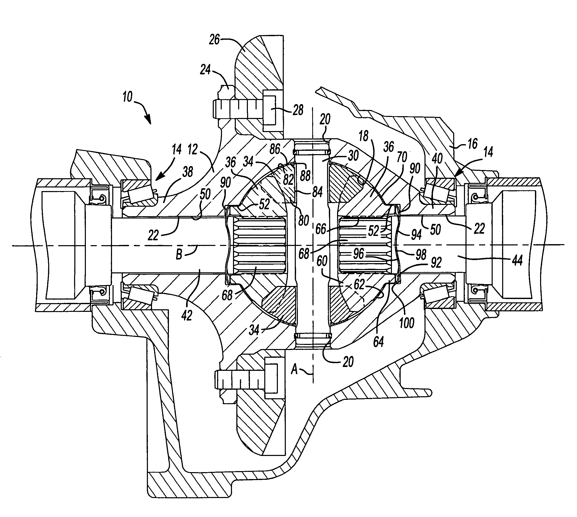
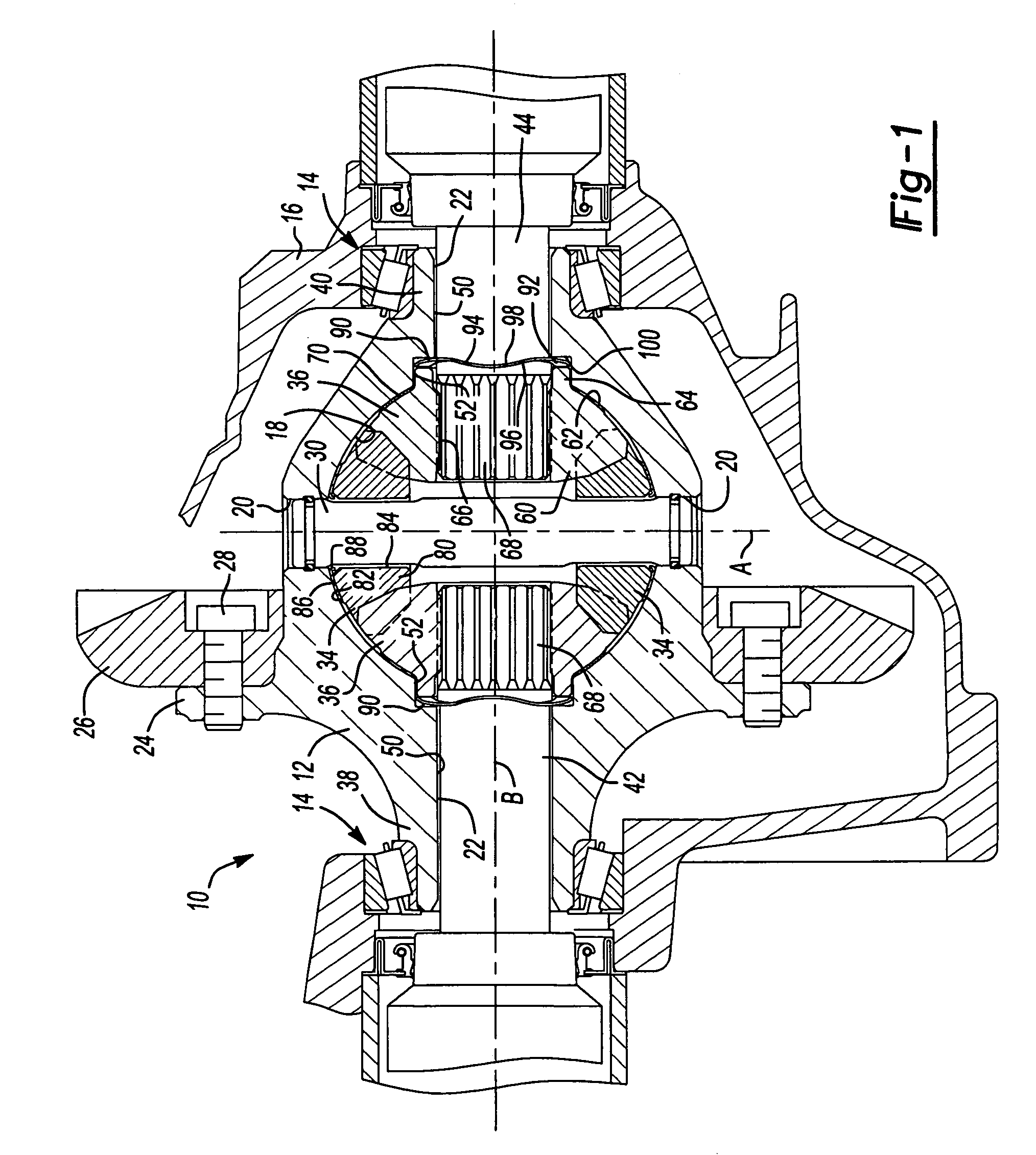
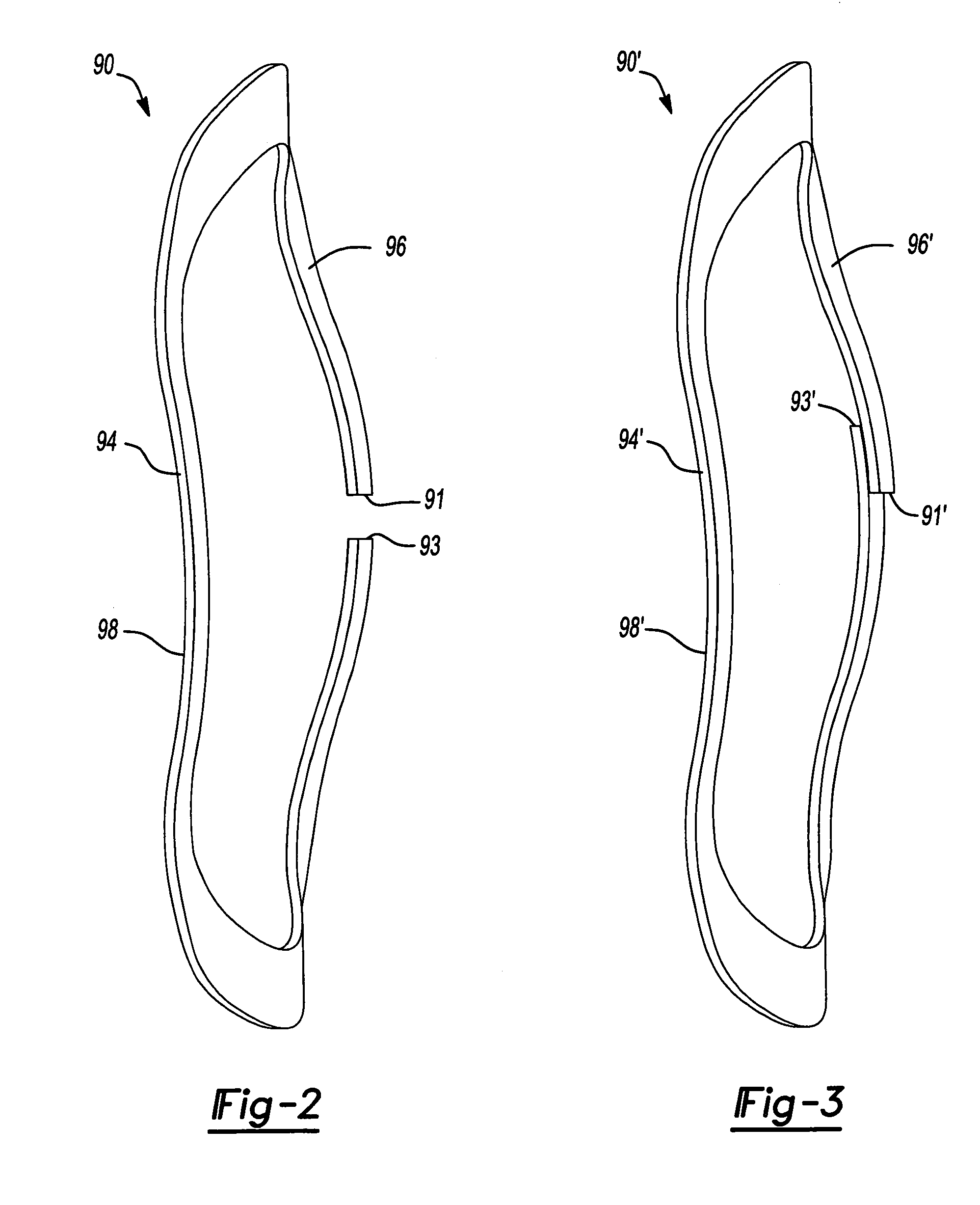
[0011]Referring to FIG. 1, a differential assembly 10 is shown to include a differential case 12 supported at its opposite axial ends by bearing assemblies 14 for rotation relative to a differential carrier or housing 16. Housing 16 can be part of an axle assembly of the type used in rear-wheel drive vehicles or, in the alternative, can be incorporated into the transaxle of a front-wheel drive vehicle. Differential case 12 is formed to include an enlarged interior chamber 18 within which a gearset is retained. Differential case 12 also includes a pair of first apertures 20 and a pair of second apertures 22, with both pairs of apertures communicating with chamber 18. In addition, differential case 12 includes a radial flange 24 to which a ring gear 26 is secured, such as by bolts 28. A pinion shaft 30 extends between firs...


PUM


Abstract

A differential assembly includes a differential housing including a substantially spherically shaped chamber. A pair of spherically shaped side gears are rotatably positioned in the chamber in driving communication with a pair of spherically shaped pinion gears. A pair of springs are positioned in engagement with the end faces of the side gears to minimize gear lash between the side gears and the pinion gears.

Description

BACKGROUND AND SUMMARY OF THE INVENTION[0001]The present invention relates generally to automotive differentials and, more particularly, to a differential assembly including spring washers to place the differential gears in a zero lash condition.[0002]Present differential assemblies are used in a drive train of motor vehicles for delivering drive torque to the wheels while permitting speed differentiation therebetween. In order to provide easily assembled and properly functioning differential gearsets, a lash or clearance is designed to exist between the pinion gears and the side gears within the differential assembly. Excessive lash has been known to cause a “clunk” sound that is sometimes audible to the driver when the vehicle changes direction of travel. While such noises emanating from the drive train may have been previously tolerated by original equipment manufacturers, the present acceptance level for such undesirable noises is low.[0003]Additionally, some presently produced ...

Claims


Application Information

Patent Timeline
Patent Type & Authority Patents(United States)
IPC IPC(8): F16H48/06
CPCF16H48/08F16H2048/385F16H2048/387Y10T74/19005F16H2057/127Y10T74/2188F16H2048/405F16H48/12
Inventor CRADIT, JEREMY L.
Owner AMERICAN AXLE & MFG
Learn More