Bipolar battery and related method

a bipolar battery and related technology, applied in the field of bipolar batteries, to achieve the effect of high reliability

Active Publication Date: 2007-10-09
NISSAN MOTOR CO LTD
View PDF16 Cites 70 Cited by
  • Summary
  • Abstract
  • Description
  • Claims
  • Application Information

AI Technical Summary

Benefits of technology

[0013]The present invention has been carried out based on such a consideration, and it is therefore an object of the present invention to provide a highly reliable bipolar battery including unit cells series-connected within the battery, capable of allowing to form electrolyte sealing portions while keeping the gaps between current-collector foils, thereby enabling the electrolyte sealing portions to electrically insulate the electrodes from each other, and to provide its related method.

Problems solved by technology

Namely, in a bipolar battery including unit cell layers stacked and series-connected within the battery unlike a typical lithium-ion battery including electrodes stacked and parallel-connected within the battery, it is likely that the unit cell layers stacked within the bipolar battery are mechanically contacted with each other to thereby cause short-circuit or contacted with each other via electrolytic solution to thereby cause liquid junction.

Method used


Image

  • Bipolar battery and related method
  • Bipolar battery and related method
  • Bipolar battery and related method

Examples


first embodiment

[0041]There will be explained hereinafter a bipolar battery and a related method according to a first embodiment of the present invention, in detail.

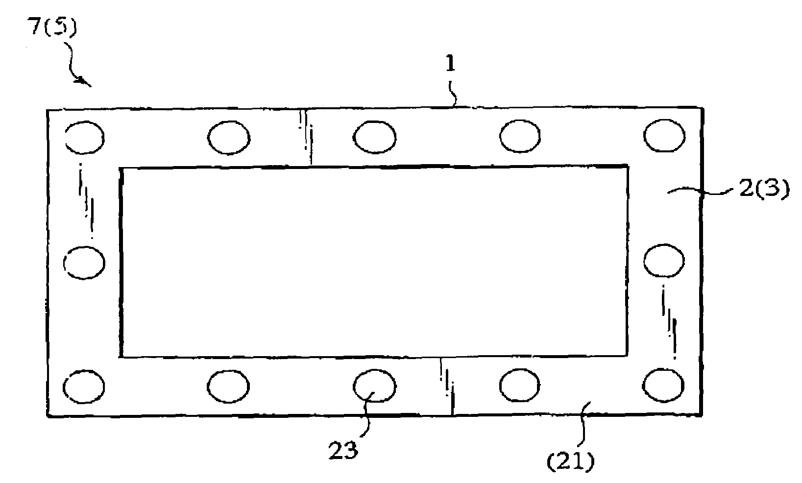
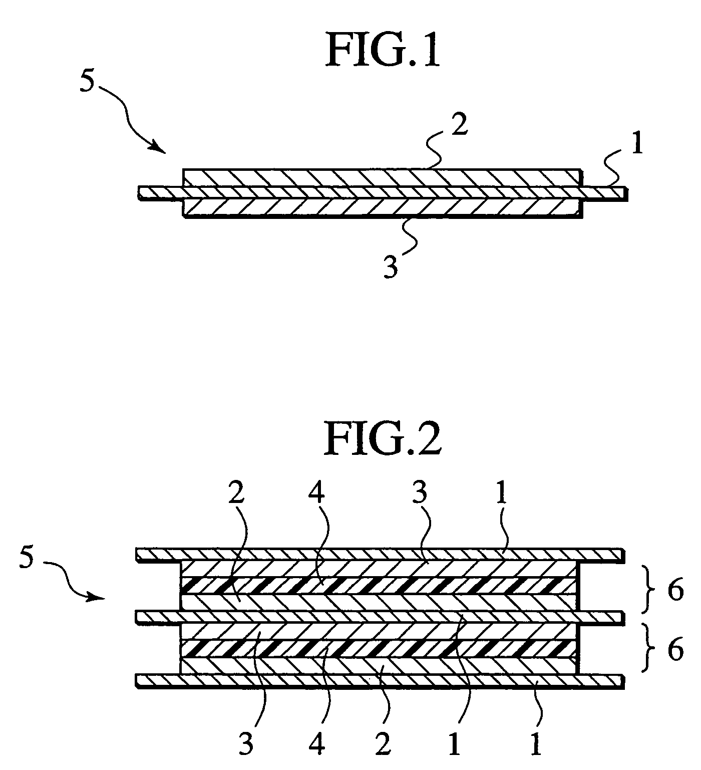
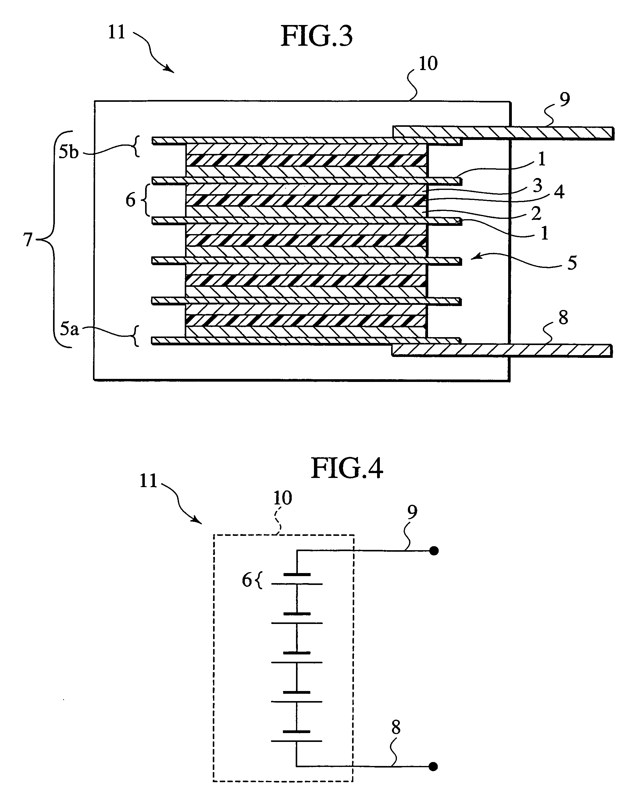
[0042]FIG. 1 is a schematic cross-sectional view of a basic structure of a bipolar electrode constituting a bipolar battery according to this embodiment; FIG. 2 is a schematic cross-sectional view of a basic structure of unit cell layers (unit cells) constituting the bipolar battery; FIG. 3 is a schematic cross-sectional view of a basic structure of the bipolar battery; and FIG. 4 is a schematic circuit diagram of the basic constitution of the bipolar battery, showing a constitution where the multiple unit cell layers stacked within the bipolar battery are series-connected. FIG. 5A is a schematic plan view of an electrode-stacked assembly arranged with multiple round-columnar spacers in the bipolar battery (the current-collector at the top-most layer is omitted); and FIG. 5B is a schematic side view of the electrode-stacked assembly of ...

second embodiment

[0178]There will be explained hereinafter a bipolar battery and a related method according to a second embodiment of the present invention, in detail. Although the basic constitution of this embodiment is the same as the first embodiment, the spacer constitution is different. There will be thus explained hereinafter such a difference in a focused manner, by designating the same components by the same reference numerals while appropriately omitting or simplifying the explanation thereof.

[0179]FIG. 9A is a schematic side view of a spacer to be used in a bipolar battery according to this embodiment, and FIG. 9B is a schematic plan view of the spacer of FIG. 9A. FIG. 10A is a schematic plan view of an electrode-stacked assembly in such a bipolar battery arranged with the multiple spacers shown in FIG. 9A and FIG. 9B (the current-collector at the top-most layer is omitted); and FIG. 10B is a schematic side view of the electrode-stacked assembly of FIG. 10A.

[0180]As shown in FIG. 9A and F...

third embodiment

[0184]There will be explained hereinafter a bipolar battery and a related method according to a third embodiment of the present invention, in detail. Although the basic constitution of this embodiment is the same as the second embodiment at the point utilizing a spacer as a continuous body, the detailed spacer constitution is different. There will be thus explained hereinafter such a difference in a focused manner, by designating the same components by the same reference numerals while appropriately omitting or simplifying the explanation thereof.

[0185]FIG. 11A is a schematic side view of a spacer to be used in a bipolar battery according to this embodiment, and FIG. 11B is a schematic plan view of the spacer of FIG. 11A. FIG. 12A is a schematic plan view of an electrode-stacked assembly in the bipolar battery arranged with a plurality of the spacers shown in FIG. 11 (the current-collector at the top-most layer is omitted), and FIG. 12B is a schematic side view of the electrode-stac...


PUM

PropertyMeasurementUnit
thicknessesaaaaaaaaaa
thicknessaaaaaaaaaa

Abstract

A bipolar battery comprises: a plurality of bipolar electrodes; electrolyte layers formed between adjacent ones of the plurality of bipolar electrodes, respectively; sealing portions surrounding and sealing the electrolyte layers, respectively; and contributing members contributing to keeping gaps between the adjacent ones of the plurality of bipolar electrodes, respectively. The contributing members are disposed within areas of the sealing portions, respectively.

Description

BACKGROUND OF THE INVENTION[0001]The present invention relates to a bipolar battery and a related method, and more particularly to a bipolar-battery and a related method utilizing polymer gel electrolyte having a higher ionic conductivity than polymer solid electrolyte.[0002]It has been recently and earnestly desired to reduce exhausted amounts of carbon dioxide, for environmental-protection. In the vehicle industry, it has been expected to reduce exhausted amounts of carbon dioxide such as by introducing electric vehicles (EVs) and hybrid electric vehicles (HEVs), and there has been thus earnestly conducted development of secondary batteries for driving the motors of such vehicles, as decisive points for bringing these vehicles into practical use. Concerning secondary batteries, attention has been directed to so-called lithium-ion secondary batteries capable of achieving higher energy and higher output densities. Only, it is required to use series-connected multiple secondary batte...

Claims


Application Information

Patent Timeline
Patent Type & Authority Patents(United States)
IPC IPC(8): H01M10/04H01M2/14H01M2/06H01M10/05H01M2/08H01M6/16H01M10/0525H01M10/0565H01M10/0566H01M10/0585H01M10/28
CPCH01M2/08H01M10/0525H01M10/0565H01M10/0585H01M10/0418H01M4/131H01M4/133H01M4/1391H01M4/1393H01M4/505Y10T29/4911Y02E60/122Y02T10/7011Y02E60/10Y02P70/50Y02T10/70
Inventor FUKUZAWA, TATSUHIRONEMOTO, KOUICHIHOSAKA, KENJI
Owner NISSAN MOTOR CO LTD
Why Eureka
Try Eureka