Micromechanical infrared source

a micromechanical and infrared source technology, applied in the field of infrared detection devices, can solve the problems of limiting the utilization of incandescent lamps, affecting the accuracy of measurement, and reducing the use of lamps, so as to avoid or reduce the need for infrared radiation in other directions

a micromechanical and infrared source technology, applied in the field of infrared detection devices, can solve the problems of limiting the utilization of incandescent lamps, affecting the accuracy of measurement, and reducing the use of lamps, so as to avoid or reduce the need for infrared radiation in other directions

US7279692B2Active Publication Date: 2007-10-09ROBERT BOSCH GMBH

Image

  • Micromechanical infrared source
  • Micromechanical infrared source
  • Micromechanical infrared source

Examples


Embodiment Construction

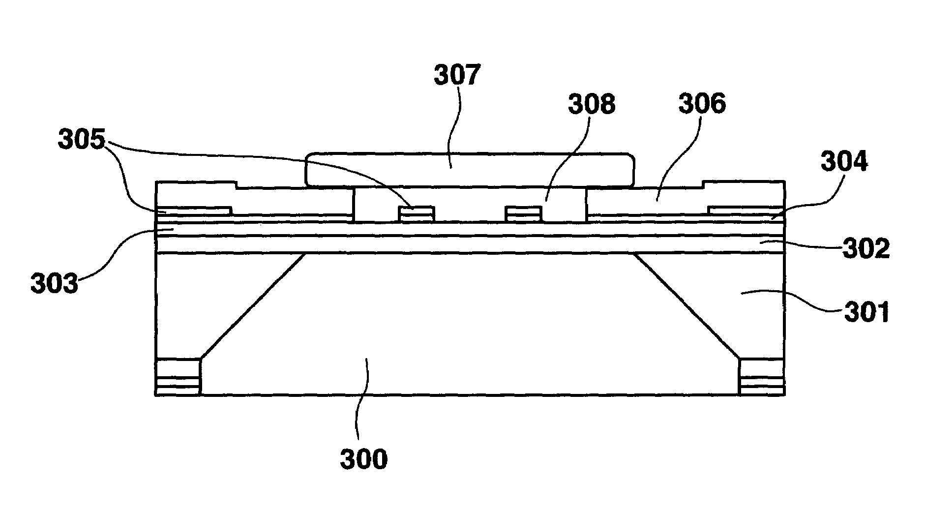
[0026]The use of a micromechanical sensor element or a sensor element manufactured using hybrid technology represents a cost-effective radiation source for a spectroscopic gas sensor or fluid sensor having an irradiation maximum in the desired MIR range. This makes it possible to omit material that absorbs in this wavelength range, such as glass, for example, in the radiation path of the IR source configured in this way.

[0027]The power consumption and the overall size of the radiation source are reduced since the predominant portion of the radiation is generated in the required wavelength range. For spectroscopic sensors, the radiation proportion of IR sources (e.g., incandescent lamps) generated in the more short-waved range is dispensed with as undesirable power loss. The yield of the desired infrared radiation is increased by omitting a cover for the radiation source having a material that absorbs in the relevant wavelength range.

[0028]A radiation source manufactured using hybrid...


PUM

PropertyMeasurementUnit
wavelength rangeaaaaaaaaaa
temperaturesaaaaaaaaaa
temperatureaaaaaaaaaa

Abstract

A device for generating infrared radiation includes at least one heating element and at least one radiating element for irradiating the infrared radiation. The heating element is a micromechanical, two-dimensional heater structure. The heating element may be applied on the radiating element using hybrid technology such that the radiation element has at least one side facing the heating element and at least one side facing away. The radiating element may be ceramic substrate.

Description

FIELD OF THE INVENTION[0001]The present invention relates generally to the infrared detection devices and more specifically to the detection of a gas or fluid using a micromechanical infrared sensor.BACKGROUND INFORMATION[0002]A spectroscopic measurement is used as a long-term stable and reproducible measuring principle in, for example, carbon dioxide sensors. The radiation of an infrared source in the MIR (mean infrared range) on a typical CO2 absorption wavelength (e.g., 4.3 μm) is compared with the radiation of the infrared source for a reference wavelength (e.g., 4 μm). Information on whether and in what concentration CO2 is present in the absorption path between the radiation source and the detector results from the comparison of the radiation intensity for the absorption wavelength and the reference wavelength.[0003]Because of economic reasons, incandescent lamps, the irradiation spectrum of which reaches into the MIR range, are frequently used as the radiation source. The mai...

Claims


Application Information

Patent Timeline
09 Oct 2007
Publication
US7279692B2
IPC
G01N21/61; G01J4/00; H01K5/02; H05B3/00; H05B3/12; H05B3/14; H05B3/26
CPC
G01N21/3504; H05B3/0052; H05B3/141; H05B3/265; H05B3/12; H05B2203/032
Inventors
ARNDT, MICHAEL; LORENZ, GERD