Objective optical element, optical pickup device, and optical information recording and reproducing device

a technology of optical elements and pickup devices, applied in the field of optical information recording and reproducing devices, can solve the problems of information not being recorded or reproduced appropriately, the quantity of the shift of the converging spot is large, etc., and achieve the effect of suppressing spherical chromatic aberration and simple method

Inactive Publication Date: 2007-10-09
KONICA MINOLTA OPTO
View PDF2 Cites 4 Cited by
  • Summary
  • Abstract
  • Description
  • Claims
  • Application Information

AI Technical Summary

Benefits of technology

[0010]With consideration of the above-mentioned problems, an object of the present invention is to provide an objective optical element, an optical pickup device and an optical information recording and reproducing device, all having compatibility of the AOD with the other optical information recording media and capable of suppressing spherical chromatic aberrations caused by wavelength differences with a simple method.
[0016]Moreover, in the first aspect, because the spherical chromatic aberrations can sufficiently be corrected without providing any fine structures such as a diffractive structure on the objective lens for correcting the spherical chromatic aberrations caused by wavelength differences, the objective lens can be molded with glass, and consequently the optical pickup device which is difficult to be influenced by temperature changes and is superior in temperature characteristic can be obtained.
[0022]Moreover, because the spherical chromatic aberrations can be sufficiently corrected without providing any fine structures such as the diffractive structure on the objective lens for correcting the spherical chromatic aberrations caused by wavelength differences, the objective lens can be molded with glass. Consequently, the optical pickup device which is difficult to be influenced by temperature changes and is superior in temperature characteristics can be obtained.
[0028]Moreover, because spherical chromatic aberrations can be sufficiently corrected without providing any fine structures such as the diffractive structure on the objective lens for correcting the spherical chromatic aberrations caused by wavelength differences, the objective-lens can be molded with glass. Consequently, the optical pickup device which is difficult to be influenced by temperature changes and is superior in temperature characteristic can be obtained.

Problems solved by technology

Moreover, for example, when the so-called mode hop, at which the wavelength of a light beam instantaneously changes, is generated at the time of increase of the power of the light beam emitted from a light source, the problem that the position of a converging spot formed on an optical axis shifts from an information recording surface of an optical disc into an optical axis direction is caused.
Consequently, there is the problem that the quantity of the shift of the converging spot is large.
However, because the publication does not disclose any techniques for correcting the spherical chromatic aberration caused by a difference between wavelengths, there is the case where information cannot be recorded or reproduced appropriately when a plurality of recording media such as a high density optical disc and a DVD is used.

Method used


Image

  • Objective optical element, optical pickup device, and optical information recording and reproducing device
  • Objective optical element, optical pickup device, and optical information recording and reproducing device
  • Objective optical element, optical pickup device, and optical information recording and reproducing device

Examples


first embodiment

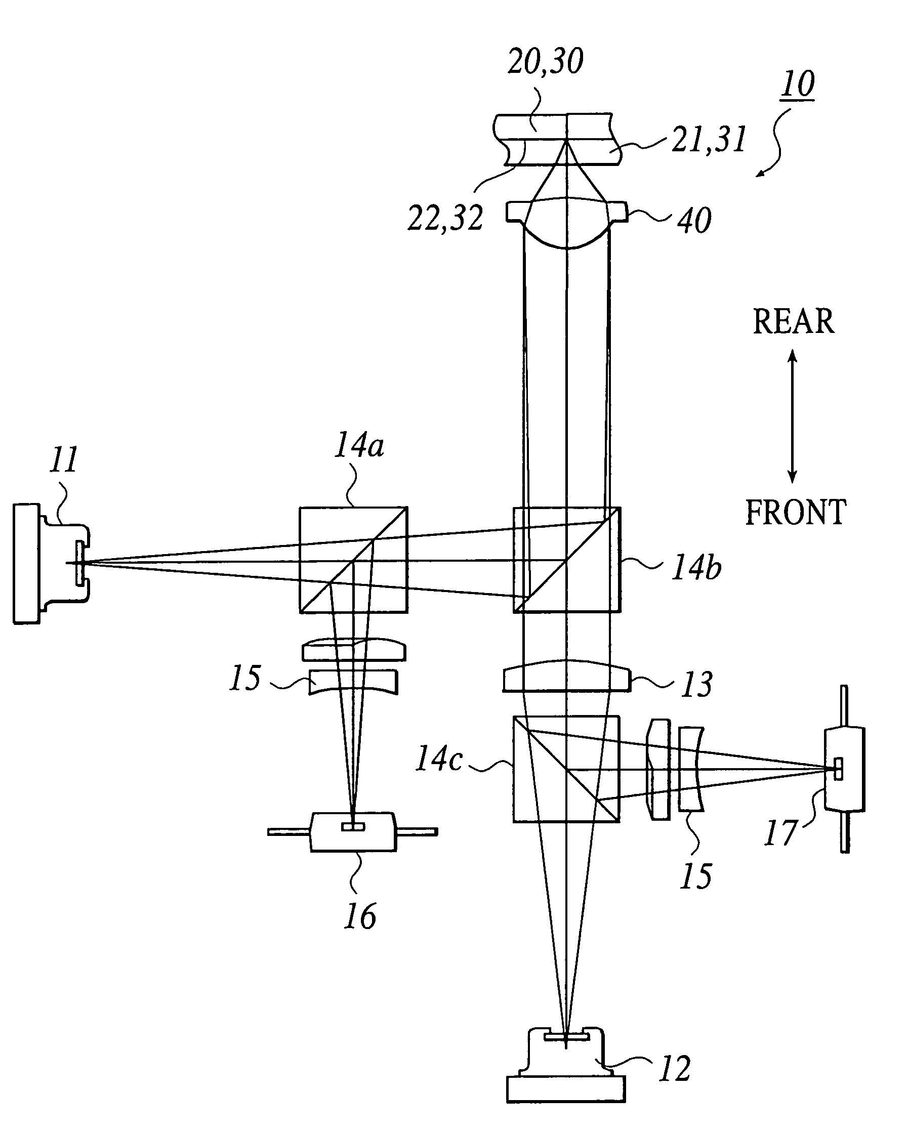
[0064]The preferred embodiments of an objective optical element, an optical pickup device and an optical information recording and reproducing device according to the present invention will be described by reference to the attached drawings.

[0065]As shown in FIG. 1, the present embodiment includes a first light source 11 and a second light source 12, which emit light beams having a wavelength λ1 (640 nm≦λ1≦670 nm) and a wavelength λ2 (400 nm≦λ2≦415 nm), respectively. The present embodiment is configured so as to have compatibility such that the recording and / or the reproducing of information can be performed to a first optical information recording medium 20 (a DVD in the present embodiment) having a protective substrate thickness t1 (0.6 mm) and a second optical information recording medium 30 (an AOD in the present embodiment) having a protective substrate thickness t2 (0.6 mm) by means of each of the light beams.

[0066]Incidentally, because the protective substrate thicknesses t1 ...

second embodiment

[0101]Next, a second embodiment of the present invention will be described in view of FIG. 6.

[0102]In the present embodiment, the protective substrate thickness t1 of the first optical information recording medium 20 (DVD) is 0.6 mm, and the protective substrate thickness t2 of the second optical information recording medium 30 (AOD) is within a range of 0.70 mm≦t2≦0.77 mm. Moreover, the optical system magnification m1 of the objective lens 40 to the light beam of the wavelength λ1 is within the range of |m1|2 to the light beam of the wavelength λ2 is also within the range of |m2|2 are almost zero. Consequently, both of the light beams of the wavelengths %l and λ2 enter the objective lens 40 as parallel light.

[0103]Incidentally, the main point of the difference of an optical pickup device 70 of the present embodiment from the optical pickup device 10 of the first embodiment is that the present embodiment is equipped with a collimator lens 60 for making the light beam having the wave...

example 1

[0106]Next, a first example of the objective lens according to the present invention will be described.

[0107]The objective lens of the present example is a plastic lens which is made from a lens material having a dispersion value νd of 58.8 and has an incidence surface and an exit surface, each being an aspheric surface.

[0108]Incidentally, though it is not shown, in the present example, aberrations are corrected well to the degree of causing no practical problems in necessary numerical apertures for a DVD and an AOD.

[0109]Lens data of the objective lens is shown in Table 1 and Table 2.

[0110]

TABLE 1Example 1νd = 58.5Variation of best focusing position 0.6 μm / nmf2 = 2.904 mmλ1 = 660 nm,λ2 = 405 nm,m1 = 0m2 = 0Surfaced1d2Numberr (mm)(mm)n1(mm)n2Remarks1∞01.001.0Iris (φ 3.90 mm)2 1.9272.51.54092.51.5604PlasticObjectiveLens3−5.5981.2531.01.0881.04∞0.61.57720.7551.6196Optical Disc5∞InformationRecordingSurface

[0111]

TABLE 2Aspheric surface dataSecond surface (aspheric surface)Aspheric surfa...


PUM

PropertyMeasurementUnit
thickness t2aaaaaaaaaa
thicknessaaaaaaaaaa

Abstract

An objective optical element to be used for an optical pickup device for performing reproducing and / or recording of information to a first optical information recording medium and a second optical information recording medium by converging a light beam having a wavelength λ1 (640 nm≦λ1≦670 nm) on the first optical information recording medium having a protective substrate thickness t1, and by converging a light beam having a wavelength λ2 (400 nm≦λ2≦415 nm) on the second optical information recording medium having a protective substrate thickness t2; wherein an optical system magnification m1 satisfies a relation of |m1|<0.01, and wherein an optical system magnification m2 satisfies a relation of |m2|<0.01.

Description

TECHNICAL FIELD[0001]The present invention relates to an objective optical element, an optical pickup device, and an optical information recording and reproducing device.TECHNICAL BACKGROUND[0002]In recent years, research and development concerning the so-called high density optical disc have been proceeding. In the high density optical disc, the recording density of an optical information recording medium (an optical disc) is increased by the use of a blue laser beam having a wavelength of about 400 nm, and then the storage capacity of the optical information recording medium is increased.[0003]As the standards of the high density optical disc, for example, a standard regulating the numerical aperture (NA) on an image side of an objective lens to be about 0.85 and the thickness of a protective substrate to be about 0.1 mm, and a standard regulating the NA and the thickness of the protective substrate to be about 0.65 and about 0.6 mm or less, respectively, at the same level as thos...

Claims


Application Information

Patent Timeline
Patent Type & Authority Patents(United States)
IPC IPC(8): G11B7/00G02B13/00G02B13/18G02B27/44G11B7/125G11B7/1275G11B7/135G11B7/1353G11B7/1374G11B7/1392
CPCG02B27/4283G11B7/1275G11B7/1374G11B7/13922G11B7/1353G11B2007/0006
Inventor ARAI, NORIKAZUSAITO, SHINICHIRO
Owner KONICA MINOLTA OPTO
Why Eureka
Try Eureka