Half rate precoded data RZ transmitter

a pre-coded data and transmitter technology, applied in electromagnetic transmission, electrical equipment, transmission, etc., can solve problems such as undesirable frequency chirp, and achieve the effects of preventing frequency chirp spreading, minimizing the spreading effect of frequency chirp, and little or no energy spread

Inactive Publication Date: 2007-10-09
OPNEXT SUBSYST
View PDF17 Cites 16 Cited by
  • Summary
  • Abstract
  • Description
  • Claims
  • Application Information

AI Technical Summary

Benefits of technology

[0015]An advantage of the present invention is that half-rate precoder and modulator driver circuits are used for generating full-rate duobinary modulation on an optical signal from which the original data can be simply detected without decoding. Because the modulator drive signals are binary, another advantage is that the modulation drivers can be operated as nonlinear amplifiers.
[0016]A duobinary optical signal has three states—a low (zero) field state, a positive field state having a phase angle of 0 radians, and a negative field state having a phase angle of π radians. This signal is sometimes called a phase duobinary signal in order to distinguish it from an amplitude duobinary signal having three amplitudes all at the same phase. A rapid transition between phase states of an optical signal may cause frequency chirp. Frequency chirp is undesirable because it spreads the frequency band of signal energy. However, a conventional phase duobinary optical system avoids this frequency chirp by using a balanced modulator drive signal composed of two simultaneous signals for driving a dual-drive modulator. The dual-drive modulator uses the simultaneous signals for modulating two portions of an optical carrier simultaneously in equal and opposite directions of phase rotation and combines the two portions for providing the duobinary optical signal. Alternatively, a single drive balanced Mach-Zehnder modulator can internally split a single drive signal input between two waveguide arms. Each of the waveguide arms modulates a portion of the optical signal. The effect of the equal and opposite phase rotation is to cancel the optical signal during the transitions between phase states so that there is little or no phase change during the transition except when there is zero intensity at the instant in time when the duobinary optical signal flips between phase states. Because there is little no phase change except when there is zero intensity, there is little or no energy spread by the frequency chirp in a conventional duobinary system.
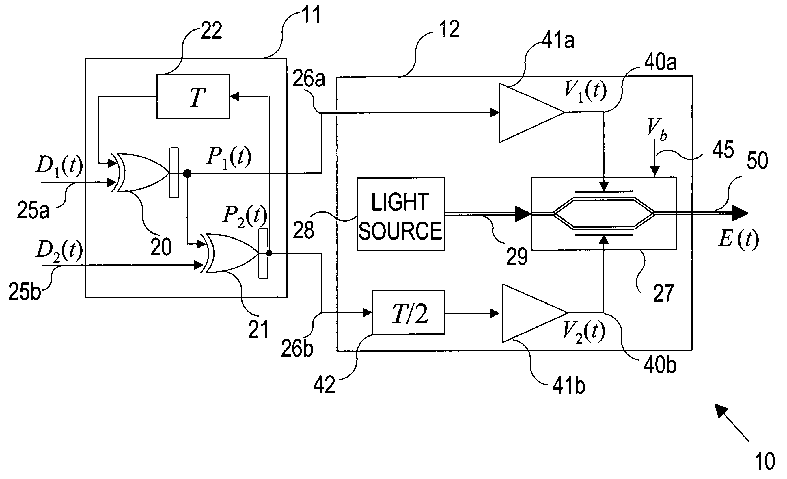
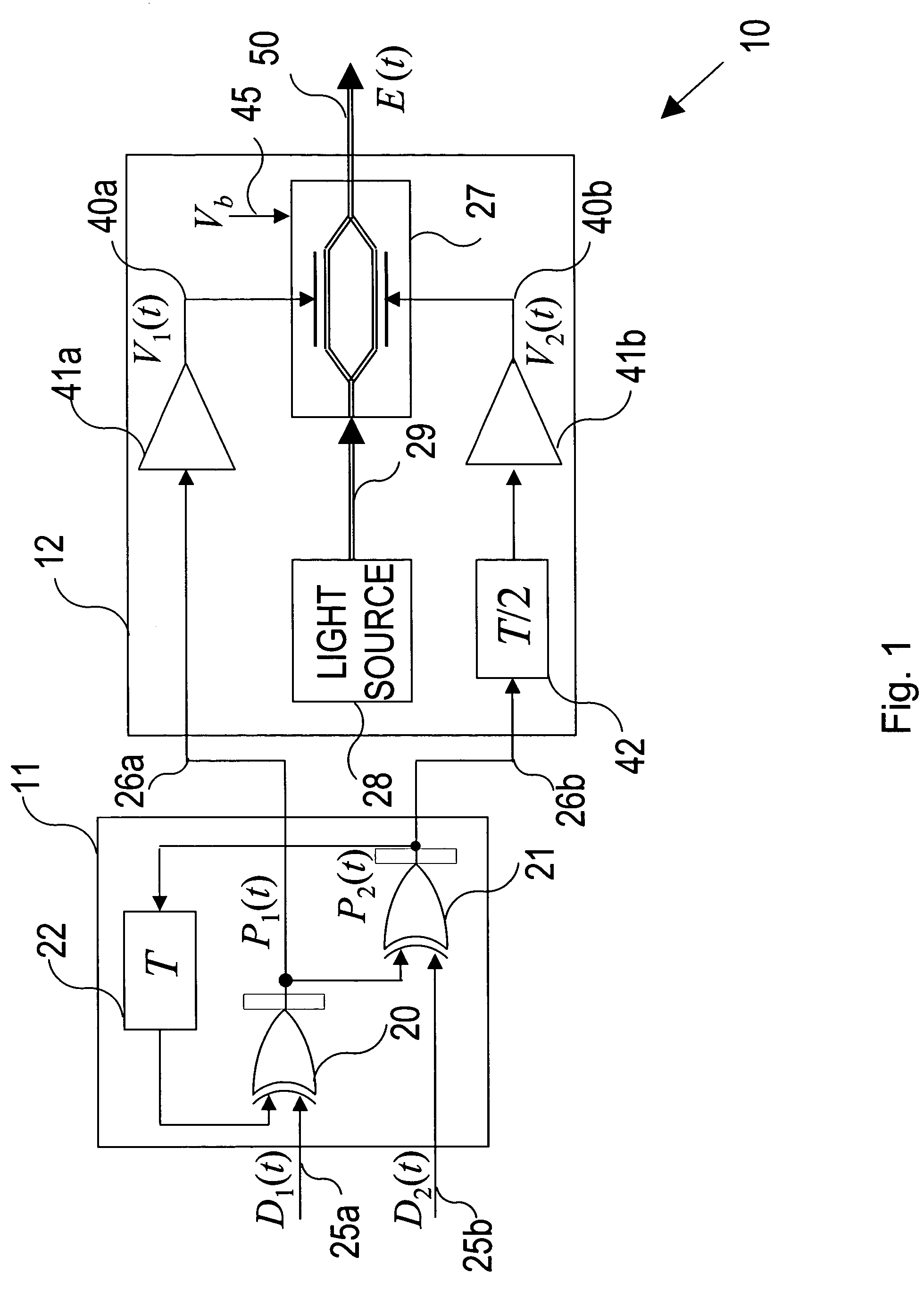
[0017]The present invention of a phase duobinary optical system also uses a modulator drive signal composed of two signals for driving a dual-drive modulator. However, in the present invention the two signals may occur one at a time. The dual-drive modulator uses the two signals independently for modulating two portions of an optical carrier for making independent transitions from one phase state to another and combines the two portions for generating the duobinary output optical signal. Because the drive signals may occur one at a time, the present invention does not avoid frequency chirp by canceling the optical signal in the conventional manner with equal and opposite phase rotations during the state transitions.
[0018]In order to prevent frequency chirp spreading for the present invention, a preferred embodiment of a multiplex modulator includes a return-to-zero (RZ) modulator. The RZ modulator uses a half rate clock drive signal for providing an RZ light signal to the dual-drive modulator or single drive balanced modulator. The dual drive modulator modulates the RZ light signal with modulation drive signal, as described above, corresponding to the difference between the one-half symbol delayed cumulative cross parity stream-stream and the other cumulative cross parity stream for providing an RZ duobinary optical signal having an optical electric field having an intensity that may be detected symbol-by-symbol for recovering the original data in the two input data streams. The clock drive signal is timed so that the RZ duobinary output optical signal has full intensity during mid-symbol times and little or no intensity during the state transitions, thereby minimizing the spreading effect of the frequency chirp.
[0019]Therefore, an advantage of the present invention is that half-rate data processing and nonlinear modulator drivers are used for generating a full rate data duobinary optical signal from which the original data can be simply detected without decoding, while at the same time frequency chirp is avoided.

Problems solved by technology

Frequency chirp is undesirable because it spreads the frequency band of signal energy.

Method used


Image

  • Half rate precoded data RZ transmitter
  • Half rate precoded data RZ transmitter
  • Half rate precoded data RZ transmitter

Examples


Embodiment Construction

[0038]FIG. 1 shows a block diagram of a duobinary transmitter 10 of the present invention having a precoder 11 and a multiplex modulator 12. The precoder 11 uses first and second exclusive-OR gates 20 and 21, respectively, and a one-symbol delay component 22 for receiving first and second binary half-rate input data streams D1 (t), denoted by 25a, and D2(t), denoted by 25b, respectively, and computing first and second cumulative cross parity streams P1(t), denoted by 26a, and P2(t), denoted by 26b, respectively. The first and second data streams D1(t) 25a and D2(t) 25b taken together carry the full-rate data that is to be transmitted.

[0039]The first exclusive-OR gate 20 provides the first cumulative cross parity stream 26a P1(t) equal to P2(t−T)+D1(t)mod 2, and the second exclusive-OR gate 21 provides the second cumulative cross parity stream 26b P2(t) equal to P1(t)+D2(t)mod 2, where the T is a half-rate input symbol time corresponding to the symbols in the half-rate input data-str...


PUM


Abstract

An optical duobinary transmitter. The transmitter uses a half-rate precoder, half-rate non-linear modulation drive circuits and a multiplex modulator for generating duobinary modulation on an optical signal from which full-rate data can be detected without decoding. The intensity of the optical signal is modulated to be zero between data symbols.

Description

CROSS-REFERENCE TO RELATED PATENT APPLICATIONS[0001]This application is a continuation-in-part of application Ser. No. 10 / 299,425 filed Nov. 18, 2002 now U.S. Pat. No. 6,804,472. The present invention and the invention of application Ser. No. 10 / 299,425 were owned by the same entity at the time the inventions were made.BACKGROUND OF THE INVENTION[0002]1. Field of the Invention[0003]The present invention is generally related to duobinary optical signal generation and more particularly to an optical transmitter and method using half rate data streams for generating full rate modulation in a duobinary optical signal.[0004]2. Description of the Prior Art[0005]Recently, optical duobinary techniques have attracted attention for narrowing the spectrum of a transmitted optical signal and reducing the waveform distortion that is induced by optical fiber chromatic dispersion. The spectrum of the transmitted signal is reduced by a factor of about two by mapping a binary data signal to be trans...

Claims


Application Information

Patent Timeline
Patent Type & Authority Patents(United States)
IPC IPC(8): H04B10/04H04B10/155
CPCH04B10/505H04B10/5167H04B10/5055
Inventor HO, KEANGPO RICKYSAUNDERS, ROSS ALEXANDER
Owner OPNEXT SUBSYST
Why Eureka
Try Eureka