Systems and methods for separating multiple sources using directional filtering

a filtering system and filtering technology, applied in the direction of electrical transducers, instruments with desired directivity, sets, etc., can solve the problems of limited success, more difficult for users to hear, and restricted operating conditions

Inactive Publication Date: 2007-10-09
COLD SPRING HARBOR LAB INC +1
View PDF13 Cites 6 Cited by
  • Summary
  • Abstract
  • Description
  • Claims
  • Application Information

AI Technical Summary

Benefits of technology

[0014]An advantage of the invention is that source separation can be performed with the use of just one sensor. The elimination of the need to use multiple sensors is beneficial, especially when considering the miniaturization trend seen in conventional electronic applications. However, if desired, source separation can also be performed using multiple sensors.

Problems solved by technology

However, because hearing aids receive all sound impinging on its receiver, it amplifies desired sounds (e.g., conversation) and undesired sounds (e.g., background noise).
Such amplification of all received sounds may make it more difficult for the user to hear.
Several approaches have been undertaken to separate sources through the use of machines, mathematical models, algorithms, and combinations thereof, but these approaches have achieved limited success or are bound by restrictive operating conditions.
Although these multiple sensor techniques may be used to separate sources, they fail when used in connection with a single sensor.
Single sensor source separation techniques have been attempted, such as those described in the Journal of Machine Learning Research (hereinafter “JMLR”), Vol. 4, 2003, and in particular, pages 1365-1392, and in Advances in Neural Information Processing Systems (hereinafter “ANIPS”), Vol. 13, 2001, and in particular, pages 793-799, but these techniques require detailed knowledge of the sources and fail to use directional filtering as a cue in performing source separation.

Method used


Image

  • Systems and methods for separating multiple sources using directional filtering
  • Systems and methods for separating multiple sources using directional filtering
  • Systems and methods for separating multiple sources using directional filtering

Examples


Embodiment Construction

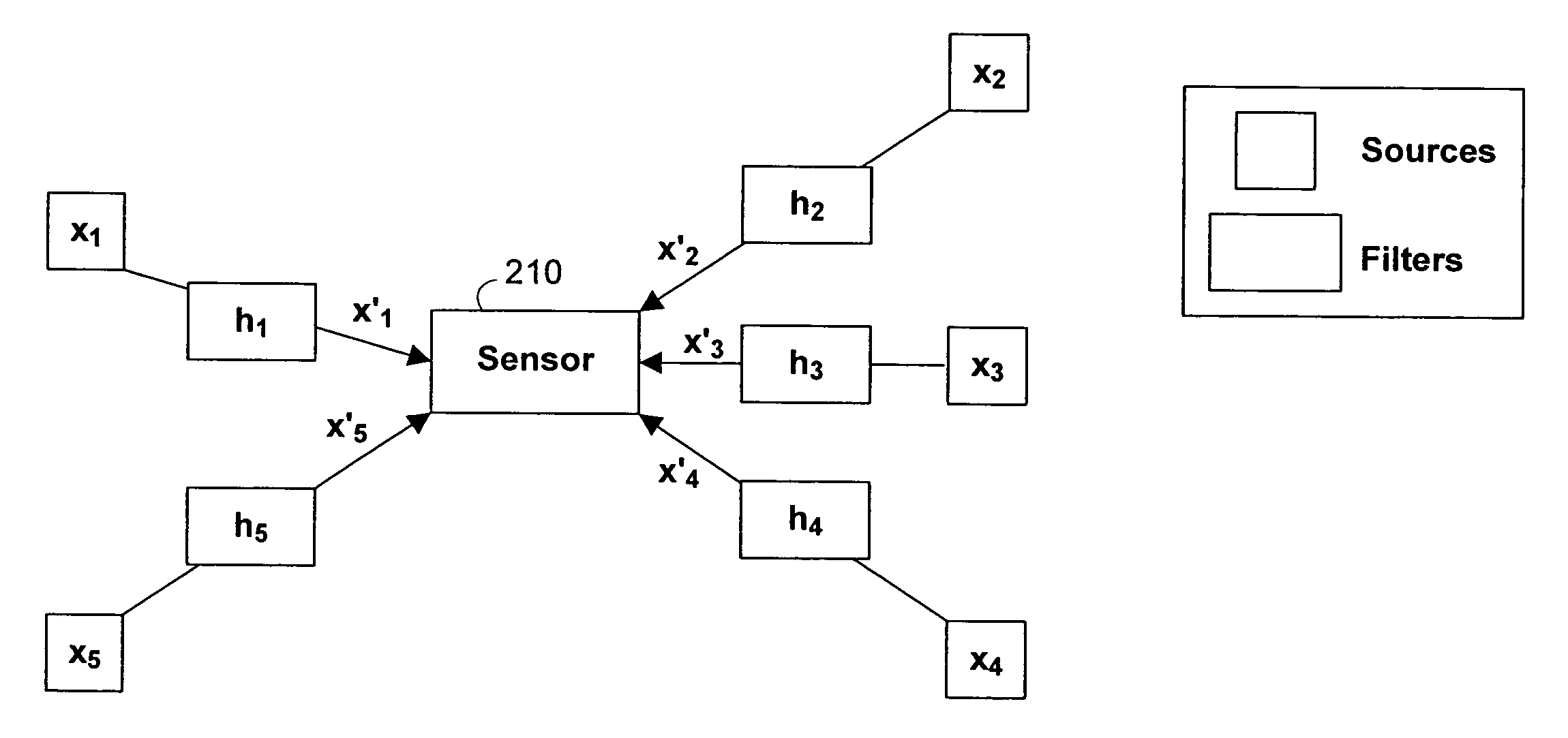
[0022]In accordance with the present invention, systems and methods are provided to separate multiple sources using cues derived from filtering imposed by the head and pinnae on sources located at different positions in space. The present invention operates on the assumption that each source occupies a particular location in space, and that because each source occupies a particular location, each source exhibits properties or characteristics indicative of its position. These properties are used as cues in enabling the invention to separate sources.

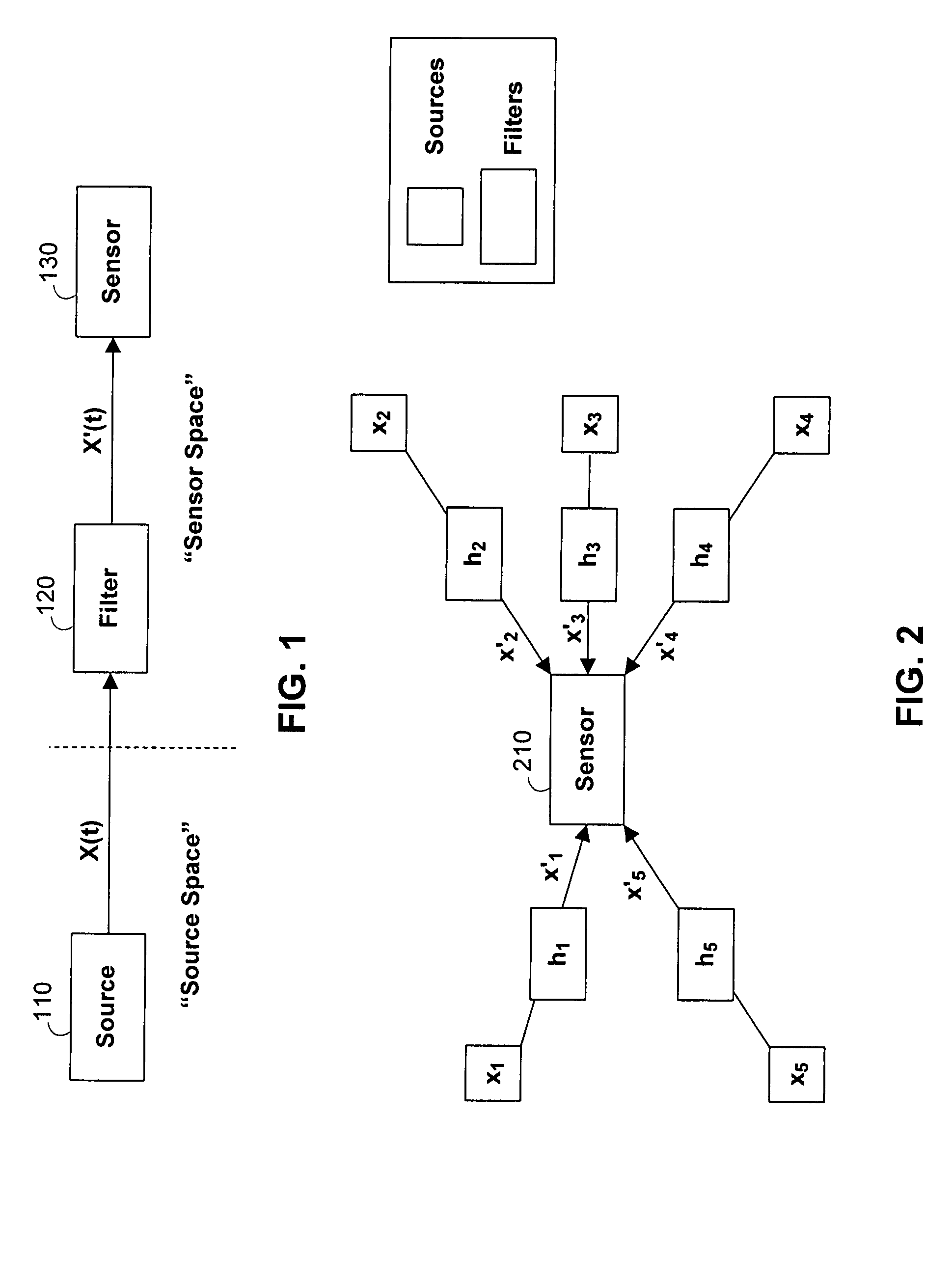
[0023]Referring to FIG. 1, source 110 emits a signal, represented here as x(t). Sensor 130 typically does not receive x(t) exactly as it is emitted by source 110, but receives a filtered version of x(t), x′(t). That is, x(t) typically undergoes a transformation, as indicated by filter 120, as it travels from the source to the sensor, resulting in x′(t). Several factors may contribute to the transformation or filtering of x(t). For example,...


PUM


Abstract

Systems and methods for performing source separation are provided. Source separation is performed using a composite signal and a signal dictionary. The composite signal is a mixture of sources received by a sensor. The signal dictionary is a database of filtered basis functions that are formed by the application of directional filters. The directional filters approximate how a particular source will be received by the sensor when the source originates from a particular location. Each source can be characterized by a coefficient and a filtered basis function. The coefficients are unknown when the sources are received by the sensor, but can be estimated using the composite signal and the signal dictionary. Various ones of the sources may be selectively reconstructed or separated using the estimated value of the coefficients.

Description

BACKGROUND OF THE INVENTION[0001]The present invention relates to systems and methods for processing multiple sources, and more particularly to separating the sources using directional filtering.[0002]There may be instances in which there are several sources emitting signals. The combination of these sources typically forms a composite signal (e.g., a signal representing a mixture of these sources) that may be received by a sensor. While there are many applications for the received composite signal, such as amplification, it is sometimes desirable to selectively isolate or separate sources in the composite signal. This problem of separating sources is sometimes referred to as the “cocktail party problem” or “blind source separation.”[0003]For example, in an acoustic environment, hearing aids may be used to amplify sounds for the benefit of the user. However, because hearing aids receive all sound impinging on its receiver, it amplifies desired sounds (e.g., conversation) and undesir...

Claims


Application Information

Patent Timeline
Patent Type & Authority Patents(United States)
IPC IPC(8): G06F15/00H04R25/00H04B3/20H04B15/00
CPCH04R25/40H04S2420/01H04R25/505H04R25/407
Inventor ZADOR, ANTHONY M.PEARLMUTTER, BARAK A.
Owner COLD SPRING HARBOR LAB INC
Why Eureka
Try Eureka