
Road surface sound reduction system

a technology of sound reduction and road surface, applied in temporary pavings, roads, construction, etc., can solve the problems of limited benefit of narrow spectrum gains of short or repetitive patterns, less than optimal apparent benefits, and overwhelming majority of noise produced

Inactive Publication Date: 2007-10-16
SCHULZ GARY
View PDF10 Cites 9 Cited by
  • Summary
  • Abstract
  • Description
  • Claims
  • Application Information

AI Technical Summary

Benefits of technology

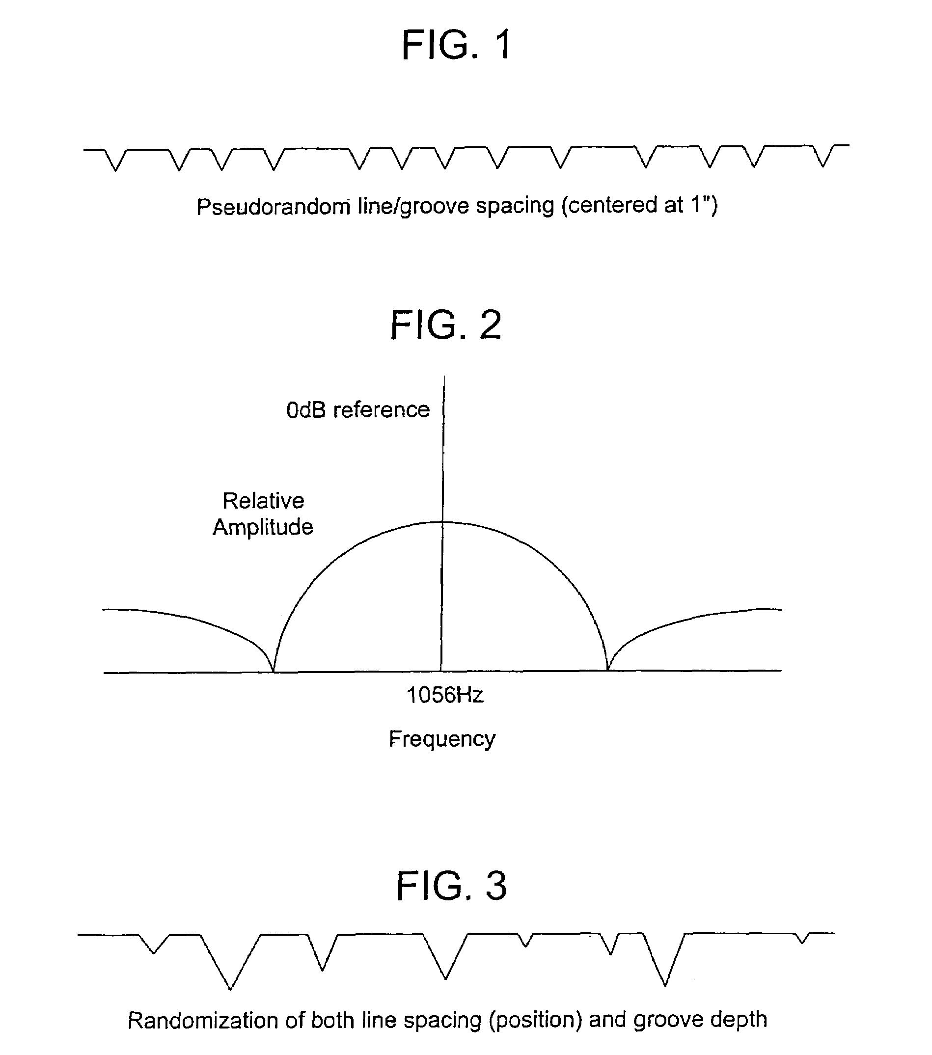
"This patent describes a way to reduce the noise generated by high-speed tires on roads. It uses a technique called spread spectrum communication, which trades peak signal power for bandwidth to reduce the signal amplitude. The technique involves creating a randomized pattern of grooves on the road surface using a specific polynomial called a maximal linear code sequence. This randomization can be done by position, frequency, or depth to spread the noise spectrum and reduce the volume of noise at any single frequency. The patent provides a mathematical description of the best practice implementation of this technique."

Problems solved by technology

Typically for an automobile that is in good operating condition with a properly functioning exhaust system, the overwhelming majority of noise is produced by the tire to pavement contact.
In both these applications acknowledgement has been made as to the effectiveness of random patterns but the apparent benefits are less than optimal due to the insufficient pattern repetition lengths and due to the fact that those patterns used were not generated by a random mathematical process.
The narrow spectrum gains of short or repetitive patterns are of limited benefit.

Method used


Image

  • Road surface sound reduction system
  • Road surface sound reduction system
  • Road surface sound reduction system

Examples


Embodiment Construction

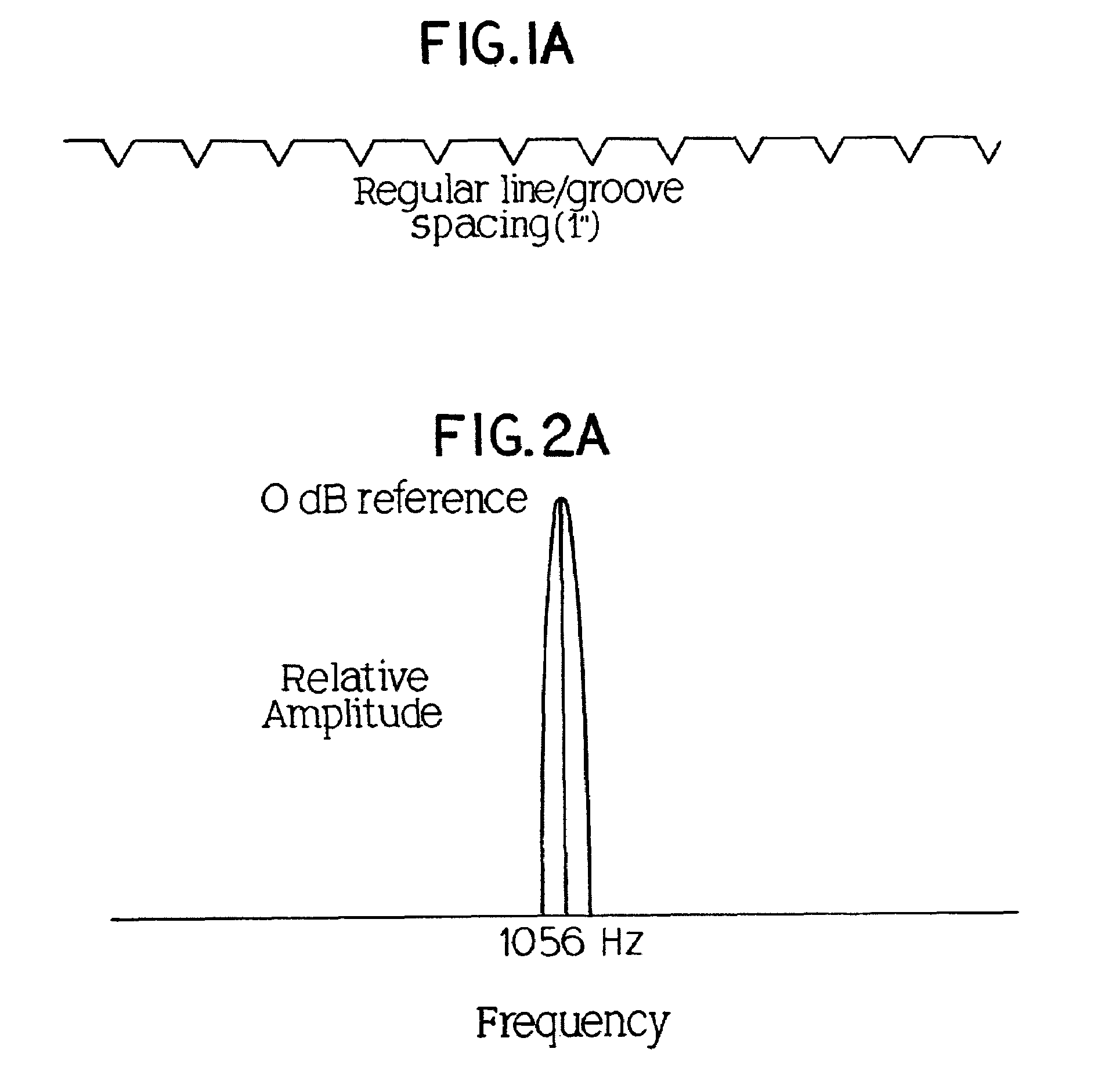
[0020]The spreading of the acoustic energy on a road surface in accordance with the present invention can be achieved by several method variations. A preferred method would be to introduce a certain amount of randomness in the spacing of the lines in the road. The amount of randomness can be relatively small and could be generated by unique line patterns that actually repeat over a spacing of as few as a couple hundred lines. This pattern can be generated by the multiplication or convolution of a pseudorandom number with the average desired line spacing (in this example spaced by about 1 inch). The preferred and most effective implementation would specifically implement a line pattern given by a polynomial of the form:

1+x+x2+x3+x4+ . . . ,

[0021]Where each x coefficient represents one unit of time delay. In this particular case it makes no difference what the unit of delay is since the technique would scale to the appropriate delay required which depends on vehicle speed. The polynom...


PUM


Abstract

A method for reducing tire to road noise generated by vehicles on a road surface comprises generating a pseudorandom unique line pattern, providing said pattern as transverse grooves disposed in the road surface, said grooves being randomized according said line pattern as to one or more of position, frequency, and depth so as to spread the noise spectrum thereby reducing the amplitude or volume of noise generated at any single frequency and are capable of dramatic reductions in noise generated by high speed traffic on roadways. It can be implemented by conventional construction practice at little or no additional cost and eliminates the need for costly structures such as noise barrier fencing in residential areas.

Description

CROSS REFERENCE TO RELOCATED APPLICATIONS[0001]This application is a continuation-in-part of U.S. patent application Ser. No. 11 / 273,422 filed Nov. 14, 2005 now abandoned, which is a continuation-in-part of U.S. patent application Ser. No. 11 / 073,066 filed Mar. 3, 2005 now abandoned, which is a continuation of U.S. Provisional Patent Application No. 60 / 589,770, filed Jul. 21, 2004. This application incorporates by reference the aforementioned prior applications.FIELD OF THE INVENTION[0002]This invention pertains to road surface noise emission by moving vehicles and more particularly to a system for reduction of the noise emitted from tires over road rolling contact.BACKGROUND OF THE INVENTION[0003]Various studies have found that the noise signature produced by traffic on any moderate to high speed roadway is composed of the following elements: 1) Tire to pavement noise due to contact between the rubber surface of the tread on a tire and the surface of the road itself; 2) Aerodynamic...

Claims


Application Information

Patent Timeline
Patent Type & Authority Patents(United States)
IPC IPC(8): E01C11/00
CPCE01C9/00E01C19/44E01C11/24
Inventor SCHULZ, GARY
Owner SCHULZ GARY
Learn More