Eureka AIR delivers breakthrough ideas for toughest innovation challenges, trusted by R&D personnel around the world.

Ball end mill

Active Publication Date: 2007-10-16
NS TOOL
View PDF12 Cites 0 Cited by
  • Summary
  • Abstract
  • Description
  • Claims
  • Application Information

AI Technical Summary

Benefits of technology

[0012]The present invention has been achieved after consideration of the problems mentioned above, and provide a ball end mill capable of highly precise cutting, while reducing abrasion and breakage of the cutting blades.

Problems solved by technology

However, the conventional ball end mill described above has problems such as the following.
In a ball end mill having two cutting blades touching at a point on the rotational axis, the contacting parts of the cutting blades have poor rigidity, making the cutting blades and the tool liable to break and shortening the life of the tool.
Providing a chisel section near the rotational axis reduces breakage of the cutting blades and the tool, however, since the cutting force in the chisel section is insufficient, the cutting blades move sideways and pressing against a work material.
Consequently, tears and the like occur in the chisel section, making it impossible to obtain a smooth cutting surface having low surface roughness.
As a result, this type of ball end mill has a drawback that it cannot be used in work requiring high precision, such as finishing.
In the end mill disclosed in the above Japanese patent application, the cutting blades are continuous, solving the problems mentioned above; however, since the circumferential speed of the cutting blades on the rotational axis is zero, the cutting resistance increases near the rotational axis, and as a result, abrasion of the cutting blades is severe, leading to breakage and shortening the life of the tool.
Furthermore, the ball end mill described in the above Japanese patent application has another drawback, namely, that the rake face and flank must be made into complex concaved surfaces, increasing the manufacturing cost.
This work is particularly difficult when using highly rigid material which is essential for highly precise cutting, and makes the manufacturing cost extremely expensive.

Method used


Image

  • Ball end mill
  • Ball end mill
  • Ball end mill

Examples


Embodiment Construction

[0035]A preferred embodiment of this invention will be described with reference to the accompanying drawings.

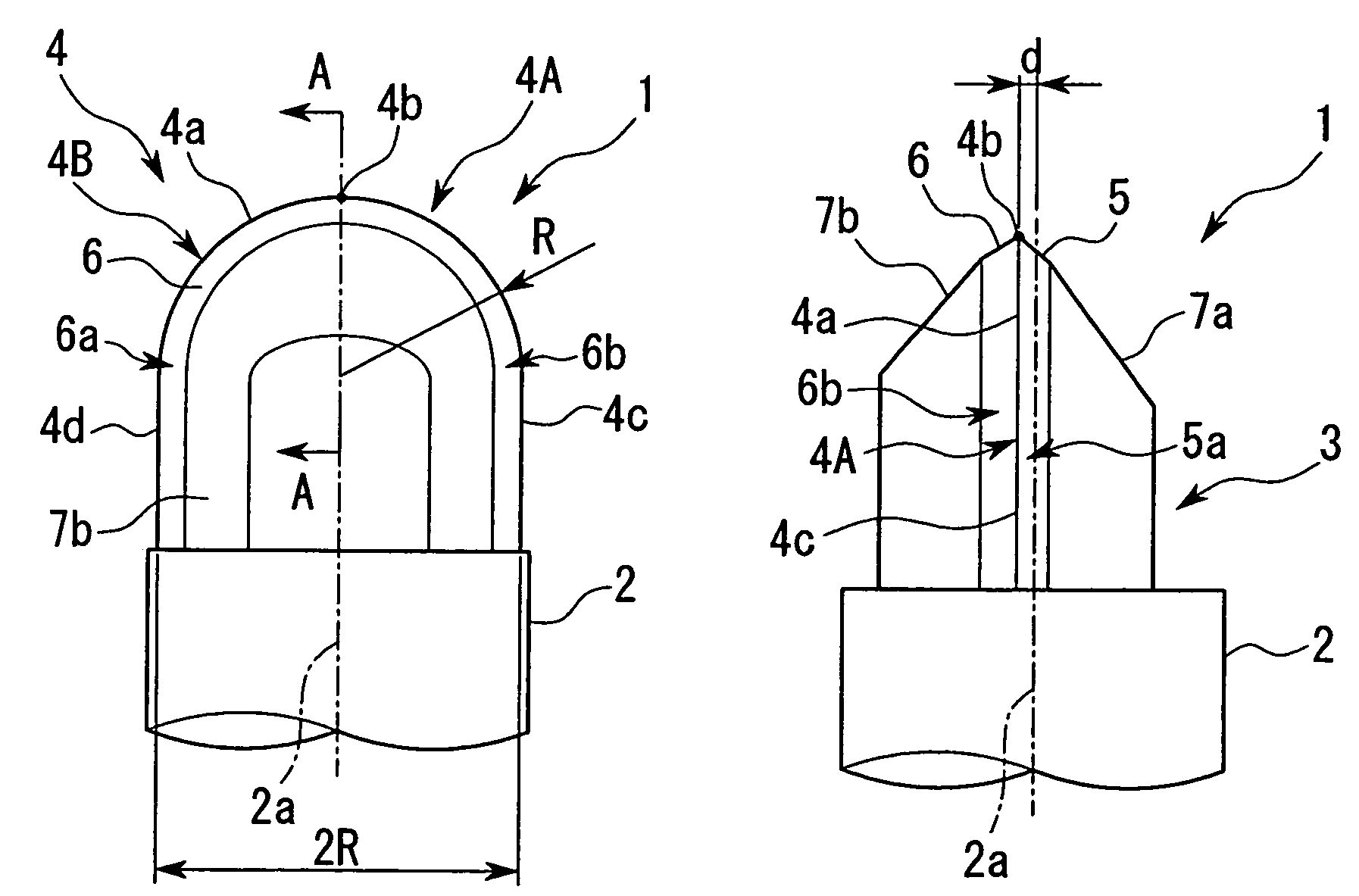
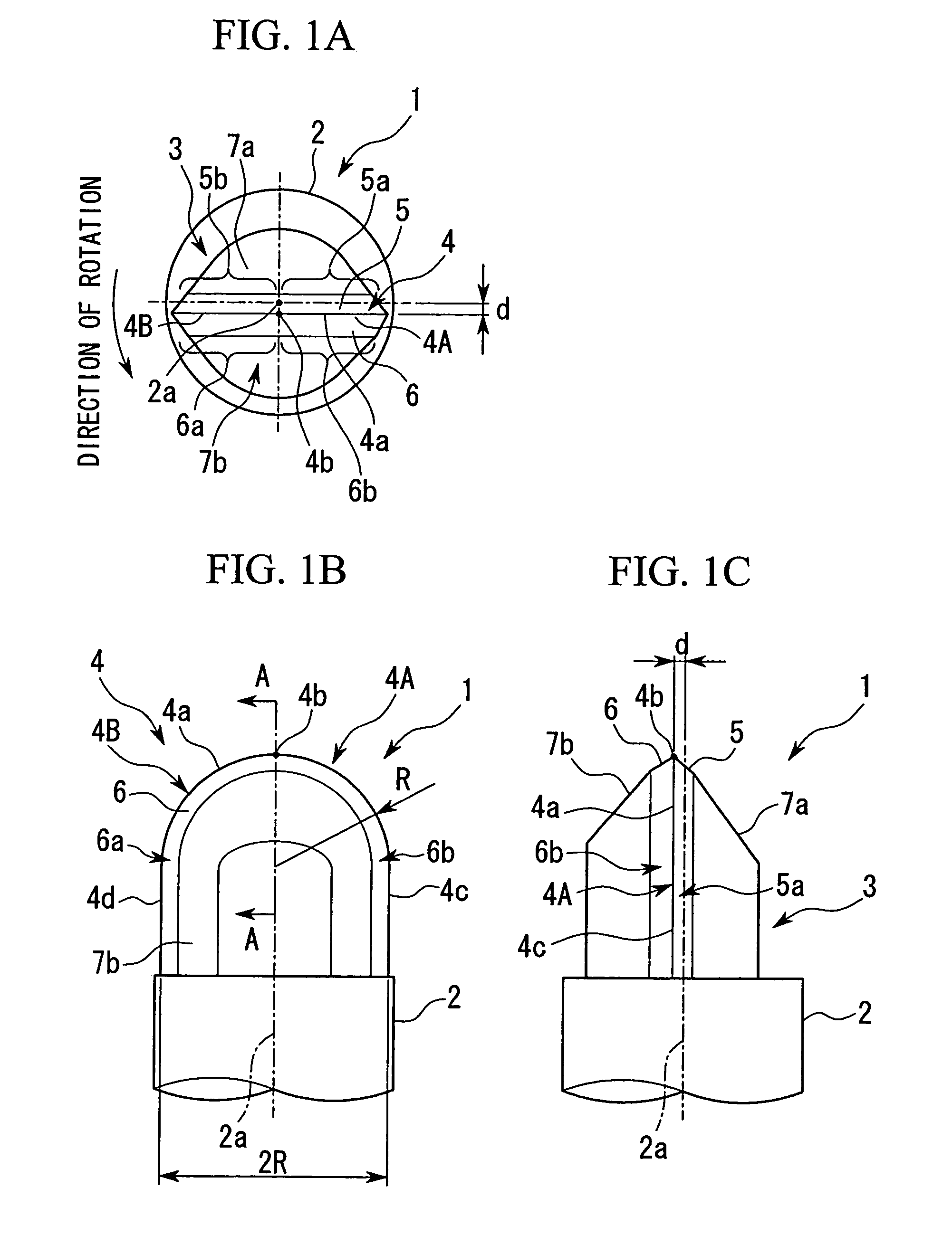
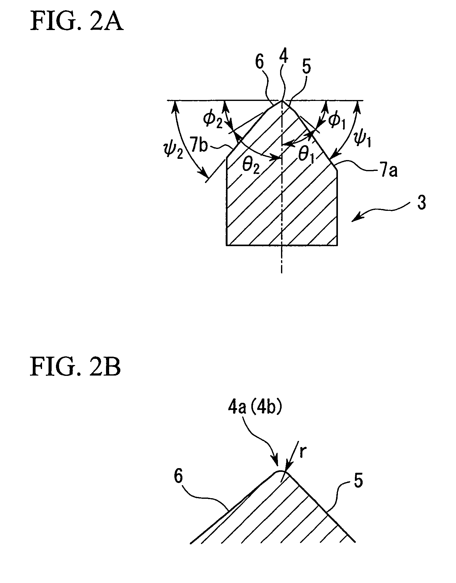
[0036]FIGS. 1A, 1B, and 1C respectively show a plan view, a front view, and a side view, of a ball end mill according to an embodiment of this invention. FIG. 2A is a cross-sectional view taken along the line A-A of FIG. 1B, and FIG. 2B is an enlarged view of this section.

[0037]The ball end mill according to the embodiment of this invention basically comprises a shank (tool main body) 2 and a cutting blade section 3.

[0038]The shank 2 is a circle-headed column-like member having a predetermined circle diameter and a predetermined length, and a shank axis 2a which constitutes a central axis of the circle-headed column exactly matches a rotational axis of the ball end mill 1 at the time of cutting.

[0039]A cutting blade section 3 is installed at the end of the shank 2, and as shown in FIGS. 1B and 1C, its tip side has a semi-circular U-shape when viewed from the front, and its ti...


PUM


Abstract

In a ball end mill, cutting can be carried out with high precision, and abrasion or breakage of the cutting blade can be reduced. The ball end mill is provided with a cutting blade section having a cutting blade, which is U-shaped in front view, at the end section of a shank. The cutting blade is provided on a flat surface deviated by a predetermined distance from the shank axis, and comprises blade faces having rake faces, which become negative angles at the time of cutting. In cross-section intersecting the cutting blade, all the blade faces have the same shape.

Description

BACKGROUND OF THE INVENTION[0001]1. Field of the Invention[0002]This invention relates to a ball end mill.[0003]2. Description of the Related Art[0004]In recent years, there have been strong demands for higher precision die molding. In response, much research and development has been conducted in relation to more precise and longer-lived cutting tools. One of these, a ball end mill, performs extremely high-precision half-spherical cutting, and is needed in cutting of the curved surface, particularly in finishing processes.[0005]A conventional ball end mill comprises two approximately quarter-circular cutting blades, which are provided opposite each other at the front tip along the diameter; the cutting blades touch at a point on a rotational axis of the end mill, or alternatively, they are given deviating rotational axes, so as to form a chisel section between the cutting blades near the rotational axis of the end mill.[0006]In the ball end mill disclosed in Japanese Patent Applicat...

Claims


Application Information

Patent Timeline
IPC IPC(8): B23C5/10
CPCB23C5/1009B23C2210/0421Y10T407/1908Y10T407/1924Y10T407/1948B23C2226/125
Inventor ISHII, SATOSHIWATANABE, TAKESHI
Owner NS TOOL
Why Eureka
Eureka Blog
Learn More