Method and an apparatus for characterizing a high-frequency device-under-test in a large signal impedance tuning environment

a high-frequency device and tuning environment technology, applied in the field of incident and reflected waveform measurement, can solve the problems of loadpull measurement methods, transistors b>14, insertion loss of directional resistive bridges, etc., and achieve low-loss directive coupling and avoid energy loss

Active Publication Date: 2007-10-16
KEYSIGHT TECH
View PDF21 Cites 55 Cited by
  • Summary
  • Abstract
  • Description
  • Claims
  • Application Information

AI Technical Summary

Problems solved by technology

One of the major difficulties of the prior art loadpull measurement methods is the generation, at the terminals of the transistor 14, of load impedances having a resistive part that is much higher or much lower than the characteristic impedance of the structures that are used to guide the microwave energy towards and away from said terminals.
The difficulty arises because of significant energy losses in the distributed directional couplers 12 and 13 or the resistive bridge structures, which are typically placed in between the transistor 14 output terminal and the tuner 15.
The insertion losses of a directional resistive bridge are caused by the resistors, which are always present in such a structure.
The disadvantage of this solution is that active tuners are expensive and difficult to control across a wide frequency bandwidth when compared to passive tuners.
Another disadvantage is that the active tuning approach has a low power handling capability when compared to passive tuners.
This limitation is caused by the inevitable saturation of the amplifiers inside the active tuning circuitry.
As a result active tuning approaches are seldom used for power levels above 10 Watt.
The disadvantage of this approach is that it is difficult to get accurate measurements of voltage and current waveforms.
This drawback is most critical when it is necessary to measure information on the harmonics that are generated by the nonlinear behavior of the DUT 14.
This results in noisy measurements, especially when the DUT 14 is saturated by a large amplitude input signal.
This causes noisy measurements with the abovementioned prior art.

Method used


Image

  • Method and an apparatus for characterizing a high-frequency device-under-test in a large signal impedance tuning environment
  • Method and an apparatus for characterizing a high-frequency device-under-test in a large signal impedance tuning environment
  • Method and an apparatus for characterizing a high-frequency device-under-test in a large signal impedance tuning environment

Examples


Embodiment Construction

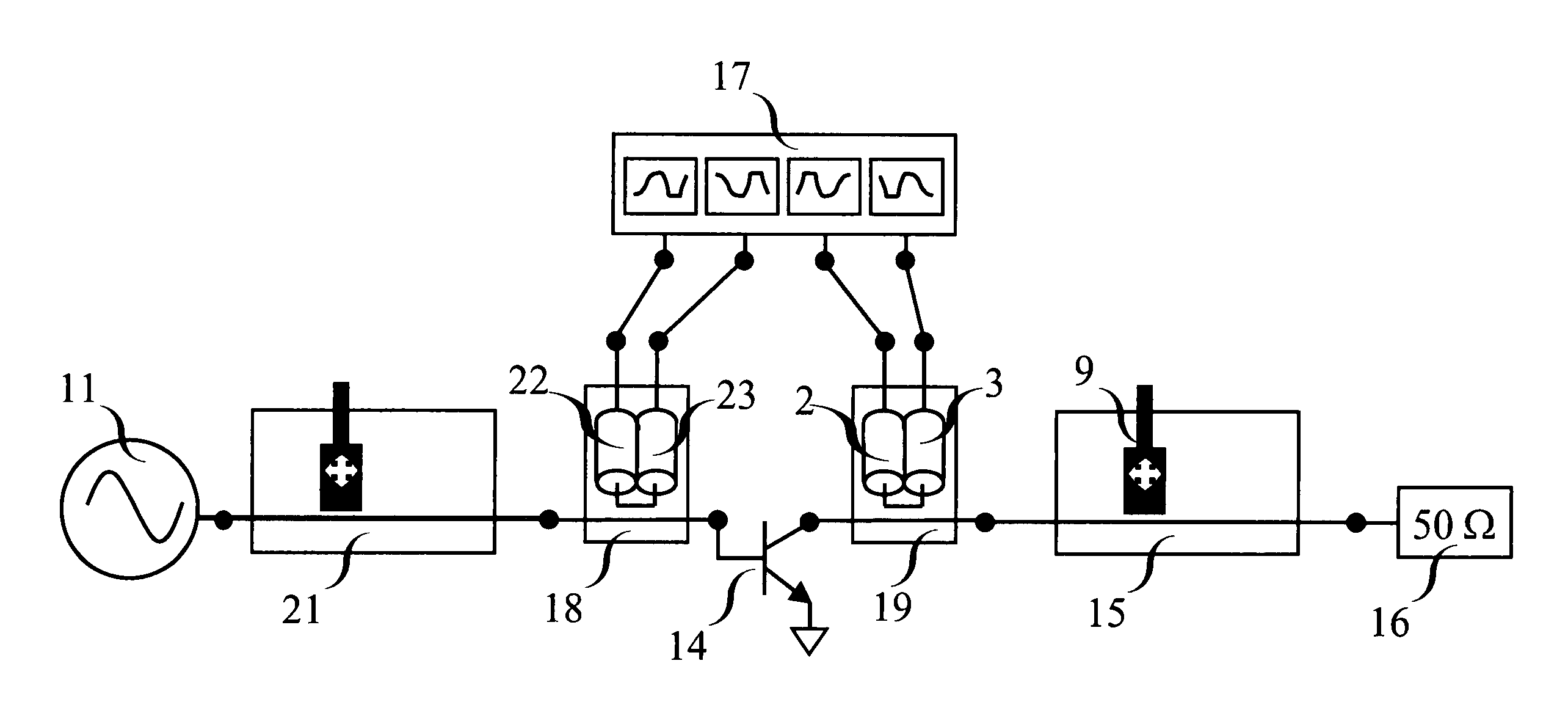
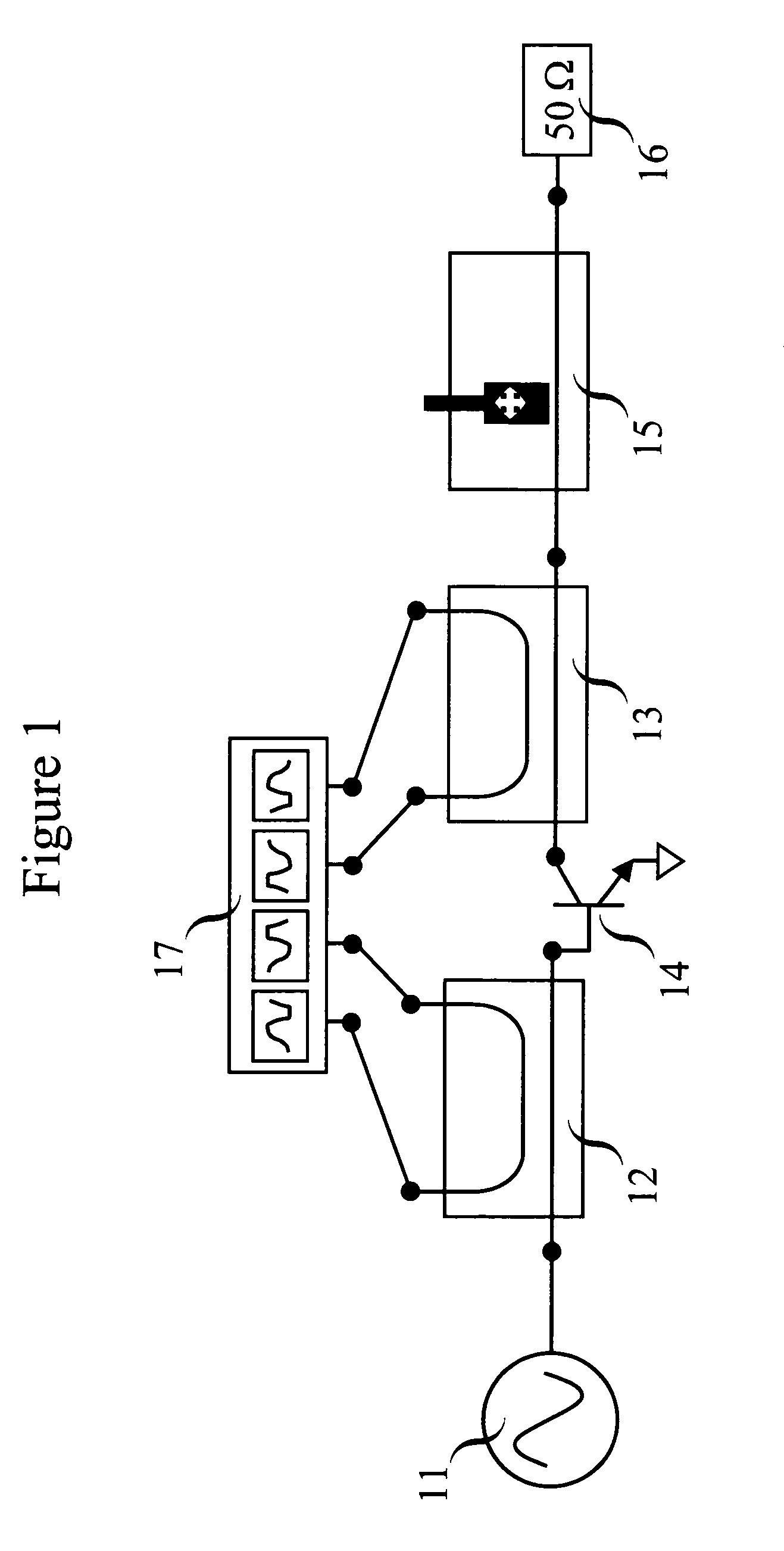
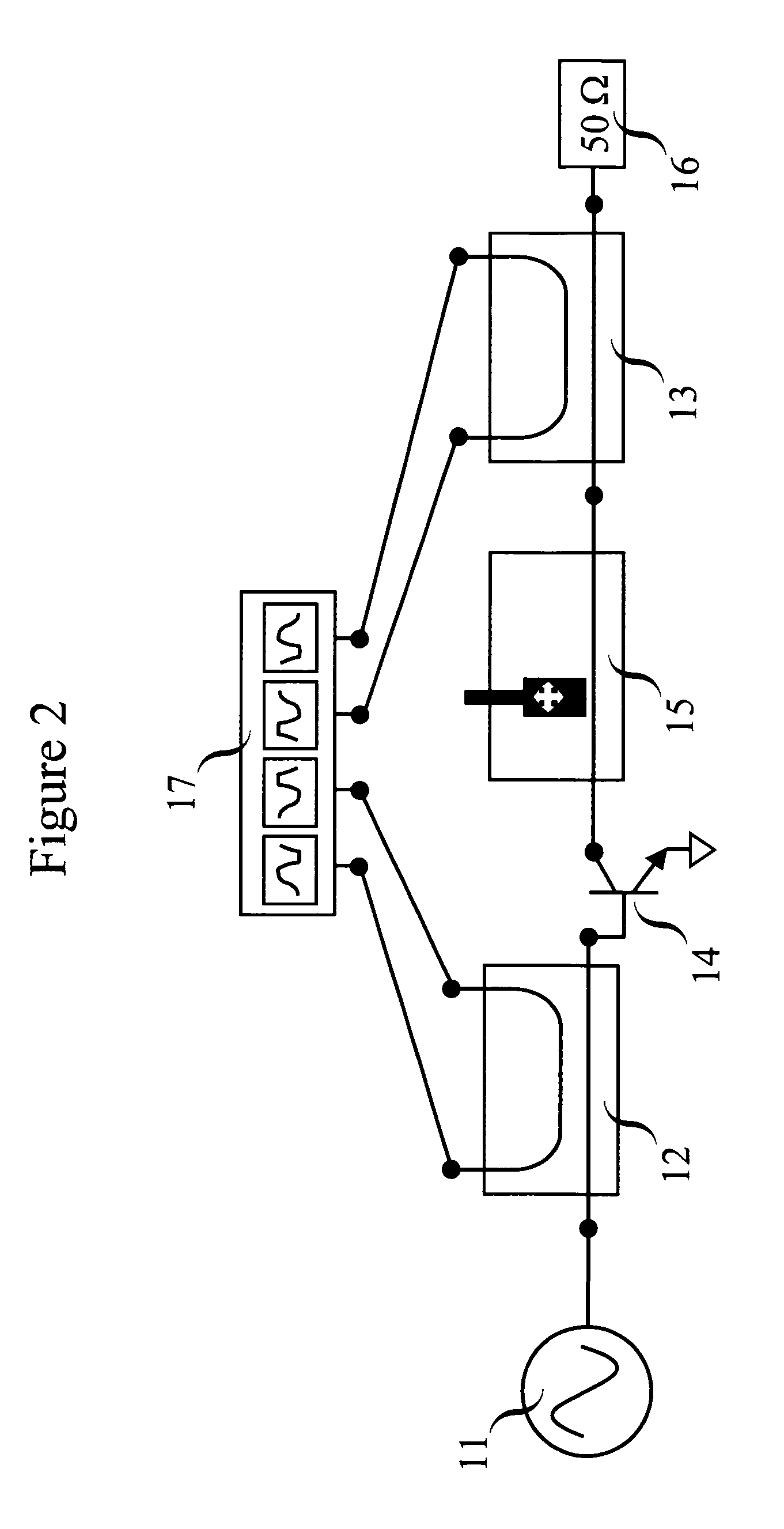
[0024]The present invention is described in “An improved coupling method for time domain load-pull measurements,” by F. De Groote, J. Verspecht, C. Tsironis, D. Barataud, J. P. Teyssier, 65th ARFTG conference digest, Jun. 12, 2005. A preferred first embodiment is depicted in FIG. 6. The invention relates to a loadpull measurement setup and method whereby one inserts an extremely low loss directive coupling structure 19 between the terminal of a device-under-test 14 and the part 9 of the tuner 15 that generates variable impedance. One hereby avoids the loss of energy caused by the distributed directional couplers 12 and 13 or the resistive bridges, which are used in the prior art as depicted in FIG. 1. The low loss directive coupling structure 19 that is used is a dual directional version of the loop type coupler described in “Criteria for the Design of Loop-Type Directional Couplers for the L Band,” by P. P. Lombardini, R. F. Schwartz and P. J. Kelly, IRE Transactions on MTT, Octobe...


PUM


Abstract

An impedance tuning measurement setup and method for characterizing high frequency devices-under-test whereby one inserts an extremely low loss directive coupling structure between the terminal of the device-under-test and that part of the impedance tuner that generates the variable impedance. One or both coupled arm outputs of the directive coupling structure are connected to the inputs of a broadband RF receiver. By using the extremely low loss directive coupling structure one avoids the loss of energy caused by the distributed directional couplers or the resistive bridges used in prior art. The low loss directive coupling structure is formed by a small piece of conductive wire, which is inserted into the electro-magnetic waveguiding structure that guides the RF signals towards and from the DUT terminals. The ends of the small piece of conductive wire are connected to the center conductors of two electromagnetic waveguiding structures, which act as the coupling arms.

Description

CROSS-REFERENCE TO RELATED APPLICATIONS[0001]Not ApplicableFEDERALLY SPONSORED RESEARCH[0002]Not ApplicableSEQUENCE LISTING OR PROGRAM[0003]Not ApplicableBACKGROUND OF THE INVENTION[0004]1. Field of Invention[0005]The present invention relates to the measurement of incident and reflected waveforms for microwave and radio-frequency (RF) devices-under-test (DUTs) under realistic large signal operating conditions.[0006]2. Description of the Related Art[0007]Modern wireless telecommunication systems use complex signals at high carrier frequencies, with frequencies typically in the GHz range. These signals are generated by electrical circuitry, like e.g. modulators and mixers that can typically only handle low power levels in the milliwatt range. The generated low power signals are amplified to a higher power level before being sent to the antenna. At the antenna power levels range from about 10 milliwatt for a cellular phone to about 100 Watt for a base station. The amplification of the...

Claims


Application Information

Patent Timeline
Patent Type & Authority Patents(United States)
IPC IPC(8): G01R27/04G01R27/32H01P5/18
CPCH01P5/04G01R27/32
Inventor VERSPECHT, JANTEYSSIER, JEAN-PIERRE
Owner KEYSIGHT TECH
Why Eureka
Try Eureka