MEMS switch stopper bumps with adjustable height

a technology of mems switch and height adjustment, which is applied in the direction of electromagnetic relays, electrostrictive/piezoelectric relays, electrical apparatus, etc., can solve the problem of much slower than solid-state switches

Inactive Publication Date: 2007-10-16
INTEL CORP
View PDF5 Cites 25 Cited by
  • Summary
  • Abstract
  • Description
  • Claims
  • Application Information

AI Technical Summary

Problems solved by technology

While RF (Radio Frequency) MEMS metal contact series switches generally have much better insertion loss and isolation characteristics, they are much slower than solid-state switches.

Method used


Image

  • MEMS switch stopper bumps with adjustable height
  • MEMS switch stopper bumps with adjustable height
  • MEMS switch stopper bumps with adjustable height

Examples


Embodiment Construction

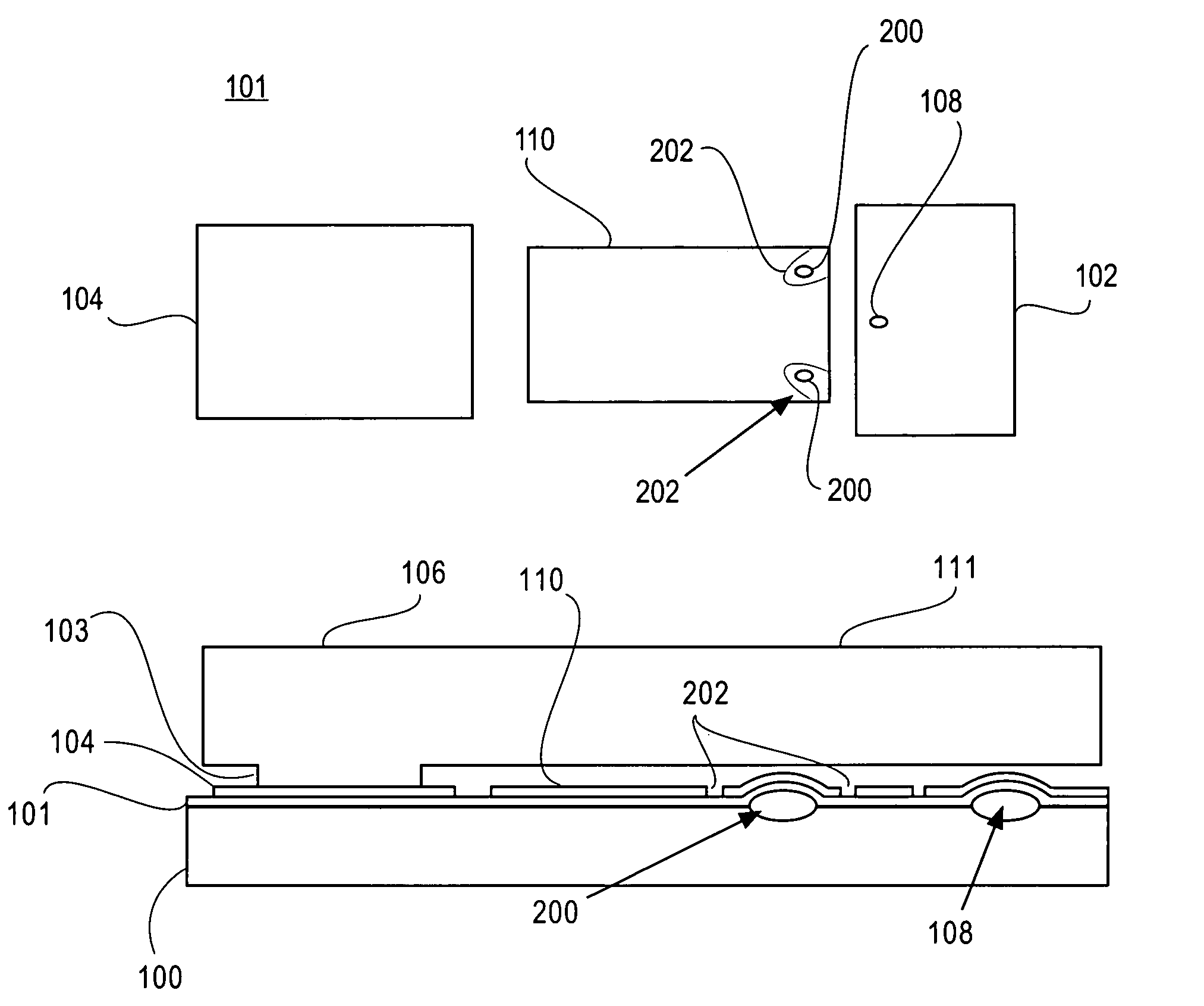
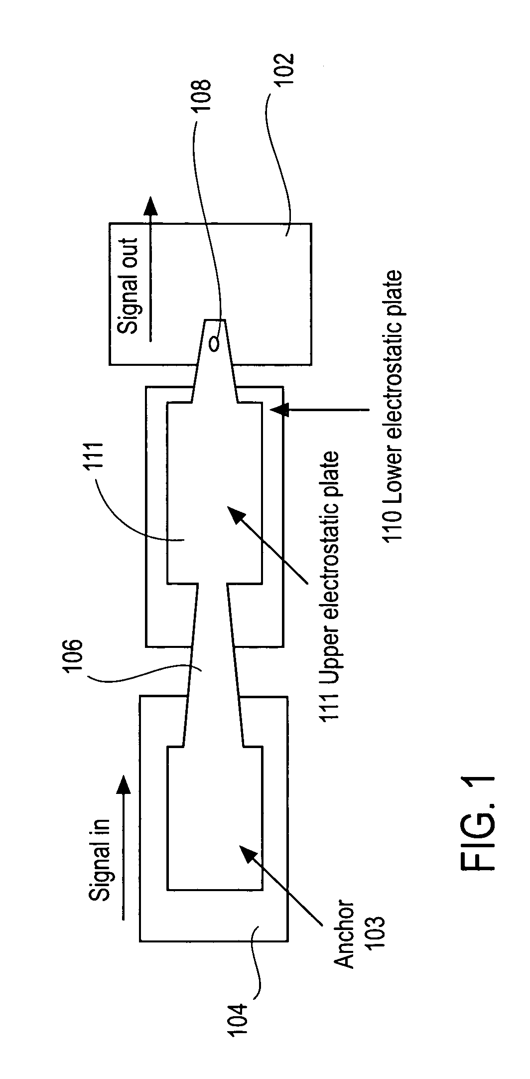
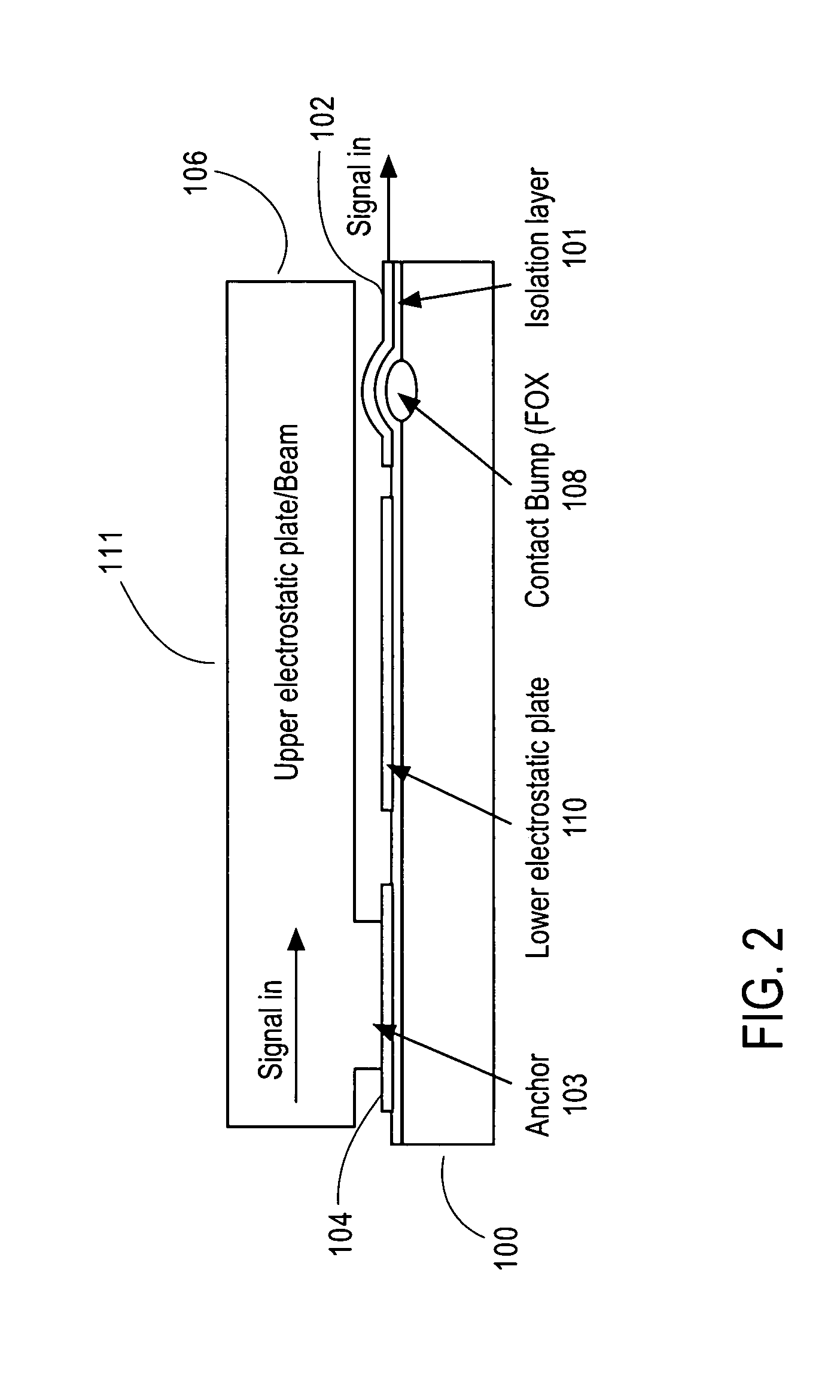
[0015]Referring now to FIGS. 4–6, there is shown one embodiment of the invention. As previously discussed, the switch is formed on a substrate 100 having an isolation layer 101. A metalized signal line 102 may be formed on one side of the substrate 100 and a second signal line 104 may be formed on the second side of the substrate 100 over the isolation layer 101. A cantilevered beam 106 may be secured to the second signal line 104 with an anchor 103. A bump (electrode) 108 may be formed for example by a field oxide (FOX) technique under the first signal line 102. A lower electrostatic actuation plate 110 may be formed on the substrate 100 beneath an upper electrostatic actuation plate 111 formed in the cantilevered beam 106.

[0016]In order to prevent shorts due, for example to torque, a stopper bump or bumps 200 are created. The stopper bump 200 may be created by addition of oxidation bumps in the bump mask, in a like manner as the contact bump 108. An isolation groove 202 is formed ...


PUM


Abstract

In a Micro Electro-Mechanical System (MEMS) switch, a common switch failure is a short between the upper and the lower electrostatic actuation plates. Such shorts may occur due to torque deformation. Stopper bumps having a slightly lower height profile than that of the contact bumps are provided to prevent such shorts. The stopper bumps may be made using the same mask as that used to create the contact bump with the height of the respective bumps controlled by determining the diameter of the bumps.

Description

FIELD OF THE INVENTION[0001]Embodiments of the present invention relate to Micro Electro-Mechanical Systems (MEMS) switches and, more particularly, to MEMS with adjustable height solder bumps.BACKGROUND INFORMATION[0002]There are many applications which require fast switching speeds. For example, for multi-mode multi-band cell phone applications such as GSM (Global System for Mobile Communications), GPRS (General Packet Radio Service), and 3G (Third Generation Wireless), the antenna switch unit switches the antenna to different bands as well as between transmission (TX) and receiving (RX) modes. Currently, solid-state switches are used for this purpose. While RF (Radio Frequency) MEMS metal contact series switches generally have much better insertion loss and isolation characteristics, they are much slower than solid-state switches.[0003]Referring to FIGS. 1 and 2, these figures illustrate a top view and a side view of a MEMS in-line cantilever beam metal contact series switch, resp...

Claims


Application Information

Patent Timeline
Patent Type & Authority Patents(United States)
IPC IPC(8): H01H51/22H01H59/00
CPCH01H59/0009H01H2059/0072
Inventor BAR, HANANHECK, JOHN
Owner INTEL CORP
Why Eureka
Try Eureka