
System and method for regulating message flow in a digital data network

a digital data network and message flow technology, applied in the field of digital communications systems, can solve problems such as message loss and message loss, and achieve the effect of fairness among all virtual circuits for buffer resources

Inactive Publication Date: 2007-10-16
AVAGO TECH INT SALES PTE LTD
View PDF18 Cites 40 Cited by
  • Summary
  • Abstract
  • Description
  • Claims
  • Application Information

AI Technical Summary

Benefits of technology

The invention provides a better way to control the flow of messages in a communication network. It involves a system with two devices connected by a network, each with a network interface for transferring messages. The destination device has a buffer to hold messages, and a flow control circuit to manage the buffer. When the buffer is full, the destination device sends a message to the source device to stop transmitting messages over a virtual circuit. The source device also has a flow control circuit to manage its buffer. This helps ensure fairness among virtual circuits and prevents message loss. The invention also includes a switching node that can forward virtual circuit flow control messages and link flow control messages to manage the buffer and prevent message loss. Overall, the invention improves the efficiency and reliability of message transfer in communication networks.

Problems solved by technology

In addition, the destination device, by transmitting link flow control messages, will ensure that the buffer does not overflow, which can result in message loss.
In addition, the switching node, by transmitting link flow control messages, will ensure that its buffer does not overflow, which can result in message loss.

Method used


Image

  • System and method for regulating message flow in a digital data network
  • System and method for regulating message flow in a digital data network
  • System and method for regulating message flow in a digital data network

Examples


Embodiment Construction

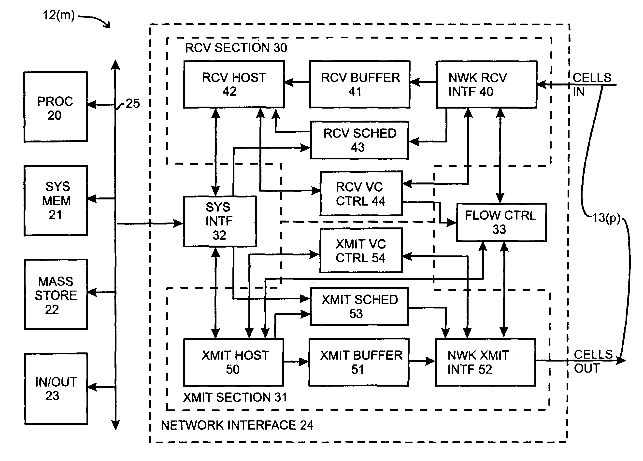
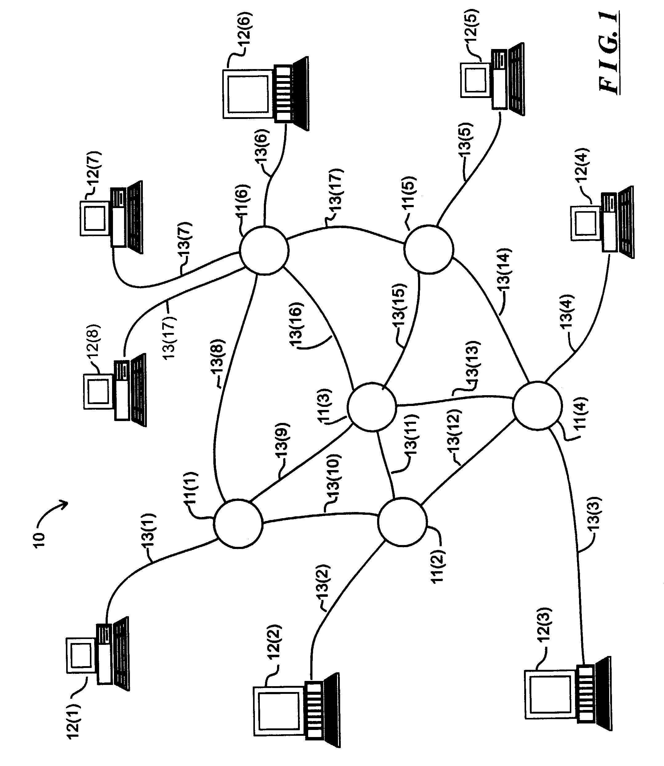
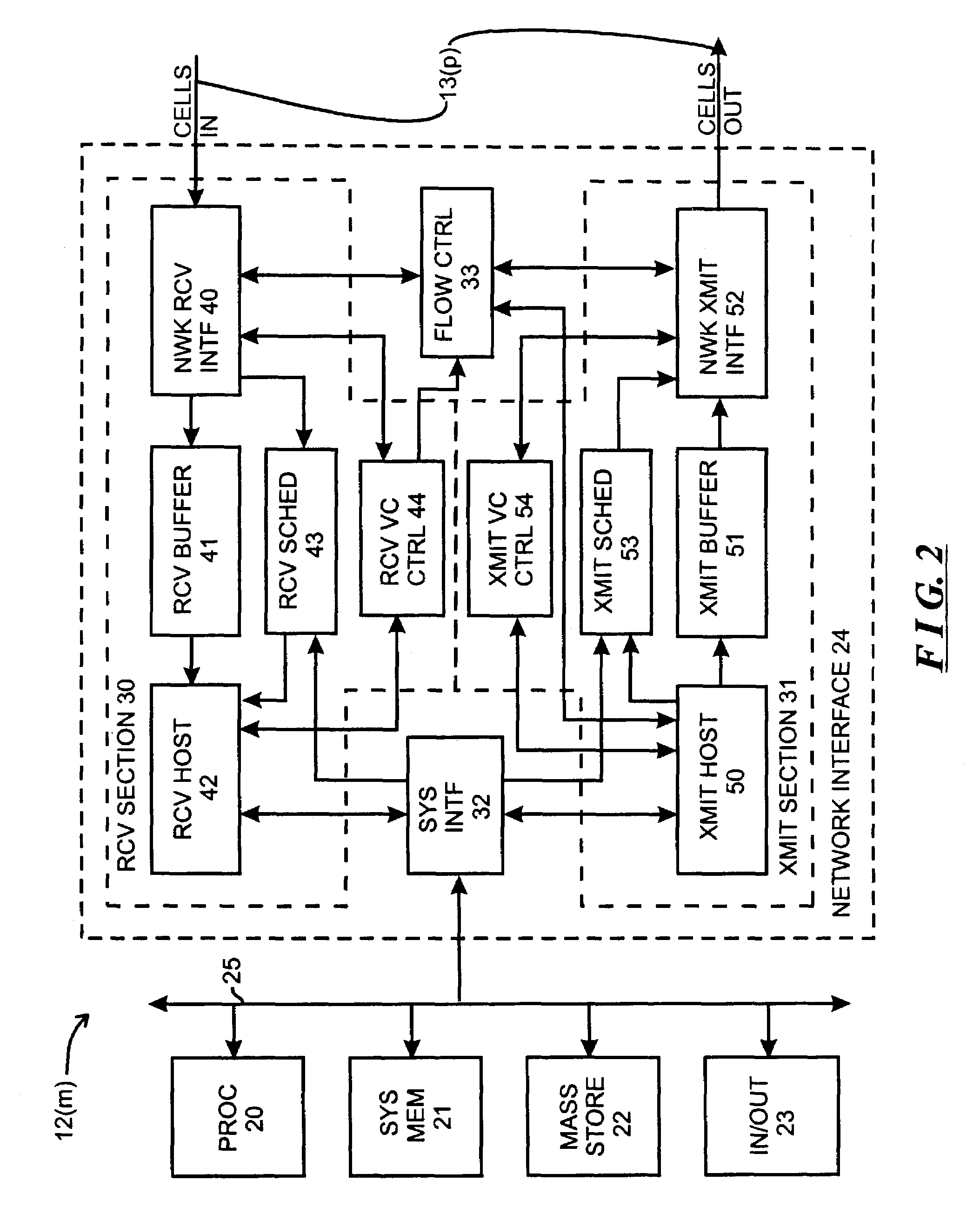
[0015]FIG. 1 schematically depicts a computer network 10 including a plurality of switching nodes 11(1) through 11(N) (generally identified by reference numeral 11(n)) for transferring signals representing data among a number of devices, which in FIG. 1 are represented by computers 12(1) through 12(M) (generally identified by reference numeral 12(m)). The computers 12(m), as is conventional, process data, in accordance with their program instructions to generate processed data. In their processing, a computer 12(mS) (subscript “S” referencing “source”) may, as a source computer, need to transfer data, processed data and / or program instructions (all of which will be referred to herein generally as “information”) to another, destination, computer 12(mD) (subscript “D” referencing “destination”), which may need to use the transferred information in its operations. Each computer 12(m) is connected over a communication link, generally identified by reference numeral 13(p), to a switching...


PUM


Abstract

A system includes a plurality of computers interconnected by a network including one or more switching nodes. The computers transfer messages over virtual circuits established thereamong. A computer, as a source computer for one or more virtual circuit(s), schedules transmission of messages on a round-robin basis as among the virtual circuits for which it is source computer. Each switching node which forms part of a path for respective virtual circuits also forwards messages for virtual circuits in a round-robin manner, and, a computer, as a destination computer for one or more virtual circuit(s), schedules processing of received messages in a round-robin manner. Round-robin transmission, forwarding and processing at the destination provides a degree of fairness in message transmission as among the virtual circuits established over the network. In addition, messages are transmitted in one or more cells, with the round-robin transmission being on a cell basis, so as to reduce delays which may occur for short messages if a long messages were transmitted in full for one virtual circuit before beginning transmission of a short message for another virtual circuit. For each virtual circuit, the destination computer and each switching node along the path for the virtual circuit can generate a virtual circuit flow control message for transmission to the source computer to temporarily limit transmission over the virtual circuit if the amount of resources being taken up by messages for the virtual circuit exceeds predetermined thresholds, further providing fairness as among the virtual circuits. In addition, each switching node or computer can generate link flow control messages for transmission to neighboring devices in the network to temporarily limit transmission thereto if the amount of resources taken up by all virtual circuits exceeds predetermined thresholds, so as to reduce the likelihood of message loss.

Description

INCORPORATION BY REFERENCE[0001]This application is a continuation of U.S. application Ser. No. 09 / 065,118, filed on Apr. 23, 1998 now U.S. Pat. No. 6,570,850; the disclosure of the prior application is considered part of (and is incorporated by reference in) the disclosure of this application.[0002]U.S. patent application Ser. No. 09 / 065,115, filed Apr. 23, 1998 in the name of Shawn A. Clayton, et al., and entitled “System And Method For Scheduling Message Transmission And Processing In A Digital Data Network”, assigned to the assignee of the instant application, incorporated by reference.FIELD OF THE INVENTION[0003]The invention relates generally to the field of digital communications systems and more particularly to digital networks for facilitating communication of digital data in, for example, digital image, audio and video distribution systems and among digital computer systems. The invention is more particularly directed to flow control and scheduling arrangements for regulat...

Claims


Application Information

Patent Timeline
Patent Type & Authority Patents(United States)
IPC IPC(8): H04L1/00H04L12/56H04Q11/04
CPCH04L12/5602H04L47/10H04L47/16H04L47/263H04Q11/0478H04L47/30H04L2012/5635H04L2012/5651H04L2012/5682
Inventor GUTIERREZ, MARIA C.CLAYTON, SHAWN ADAMFOLLETT, DAVID R.ROMAN, HAROLD E.GODIWALA, NITIN D.PROHASKA, RICHARD F.WILLIAMS, JAMES B.
Owner AVAGO TECH INT SALES PTE LTD
Learn More