
Optical router using stationary imaging

a stationary imaging and optical router technology, applied in the field of optical filters, can solve the problems of large size of each grating as compared to a conventional grating, affecting substantial loss variation, and difficult to realize, so as to reduce crosstalk and improve efficiency.

Active Publication Date: 2007-10-16
CALLAHAN CELLULAR L L C
View PDF8 Cites 9 Cited by
  • Summary
  • Abstract
  • Description
  • Claims
  • Application Information

AI Technical Summary

Benefits of technology

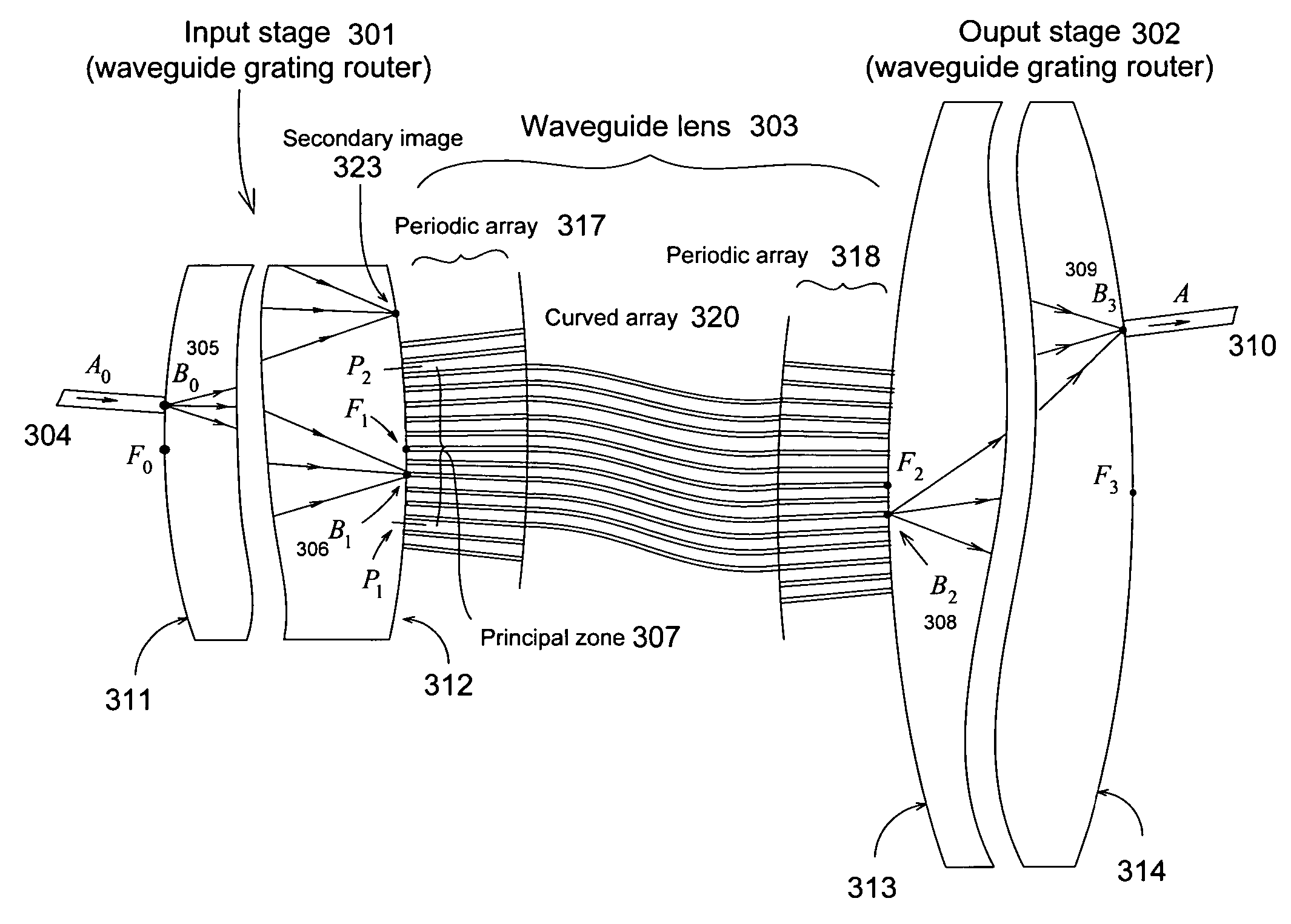
[0011]The present invention, an improved optical filter using stationary imaging, provides reduced crosstalk and improved efficiency by using a novel planar arrangement suitable for realization in integrated form. The filter is a combination of two stages. In one embodiment, the input stage is a small waveguide grating router, and the output stage includes two larger waveguide grating routers, connected to the input router by a composite waveguide lens. The lens is essentially a combination of two lenses, which are joined together on the input side, where the composite lens essentially covers the entire principal zone of the input grating. The two stages are (essentially) characterized by opposite dispersions. Therefore, the wavelength response of the filter to an input signal of variable wavelength is a set of stationary images whose output locations alternate between the two output routers. Each stationary image is produced by a particular cycle of the input router. Therefore this arrangement can be used to separate efficiently a set of input channels spaced by the cycle width (the free-spectral range λfree) of the input router. The composite lens separates the input channels in two sets, each having twice the input channel spacing. Each set is transferred by the waveguide lens to one of the two output routers. The waveguide lens is formed between three periodic arrays, respectively connected to the principal zones of the three gratings. One array (the input array of the lens) substantially covers the entire principal zone of the input grating, whereas each output array only covers a fraction (less than 1 / N where N is the number of output waveguide for each output router) of the principal zone of each output router.
[0012]The entire arrangement, shown in FIG. 5, can be realized in integrated form on a single wafer and it features low values of loss and crosstalk. It consists of an input stage 501, an output stage 502, and a composite lens 503 placed between the two stages. The input stage 501 is a small waveguide grating router whose output focal circle 512 is characterized by a central zone 521 of minimal loss variation caused by the router efficiency variation. The composite lens 503 is a waveguide arrangement characterized by a single input aperture 521 and two separate output apertures (522 and 523), wherein the input aperture covers said zone 521 of minimal loss variation. Notice the aperture 521 in FIG. 5 exactly covers the principal zone 507, but it may be convenient to choose 521 somewhat smaller than 507 to reduce adjacent channel crosstalk. The output stage 502 consists of two waveguide grating routers, each connected to one of the two output apertures of the lens. The input grating and the output gratings have opposite dispersions, and therefore the wavelength response to an input signal applied to the input router is essentially two sets of stationary images located respectively on the two output circles 514 and 516 of the output stage. The output efficiency of the input grating is optimized by including in the output periodic array of the grating suitable matching sections 435 so as to essentially produce maximally flat response in each output waveguide of the arrangement.

Problems solved by technology

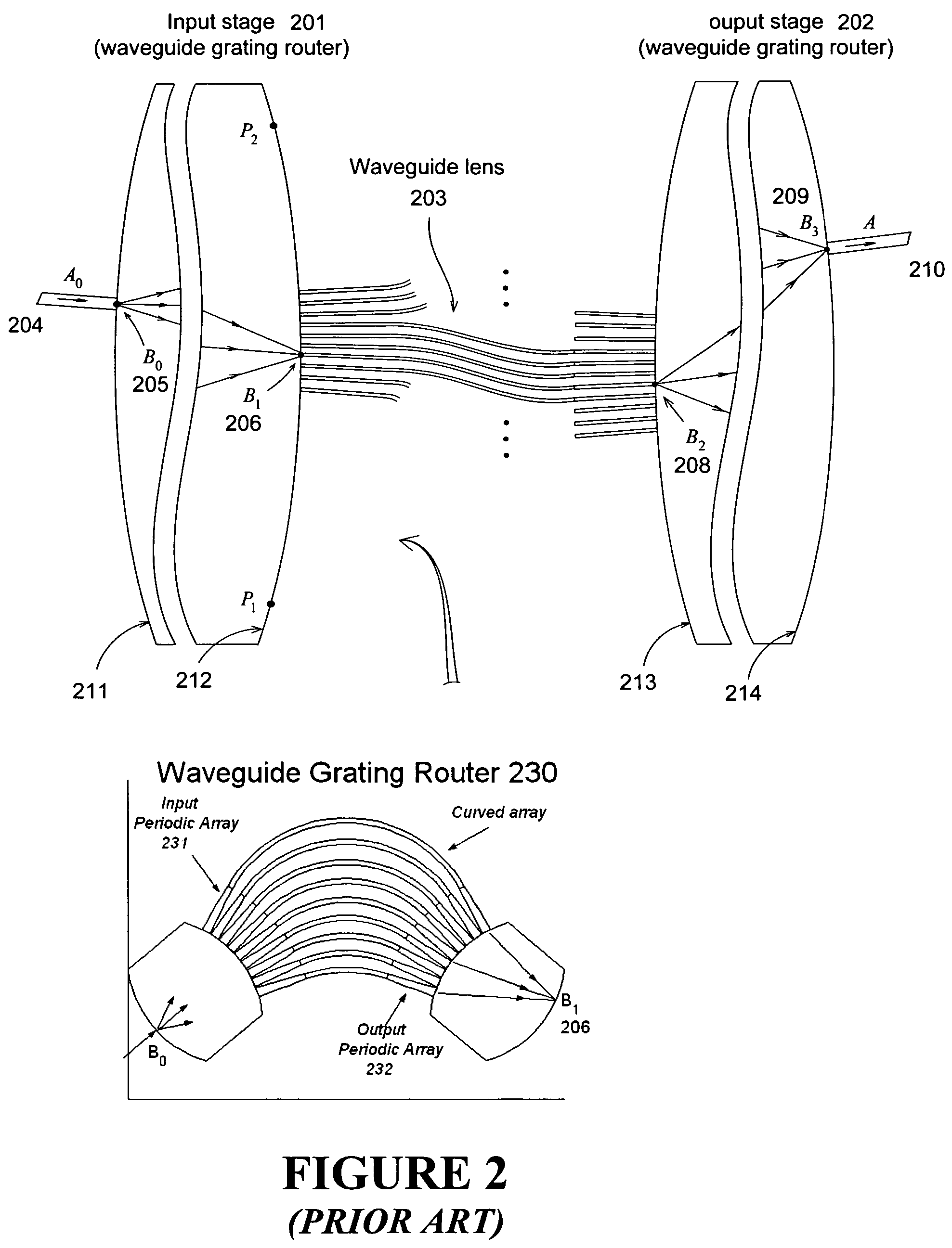
A disadvantage of the technique of FIG. 2 is the large size of each grating as compared to a conventional grating.
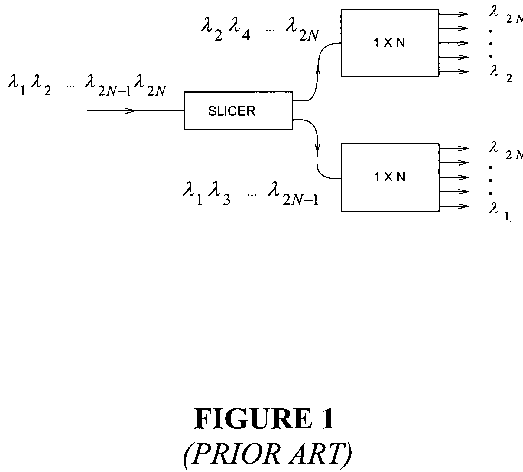
To summarize, the arrangement of FIG. 1 is difficult to realize in integrated form, and it is afflicted by substantial loss variation in each passband.

Method used


Image

  • Optical router using stationary imaging
  • Optical router using stationary imaging
  • Optical router using stationary imaging

Examples


Embodiment Construction

[0022]In the following description, identical element designations in different figures represent identical elements. Additionally in the element designations, the first digit refers to the figure in which that element is first located (e.g., 201 is first located in FIG. 2).

Router Description

[0023]An important function that must be provided in high quality optical networks is that of wavelength multiplexing and demultiplexing. In particular, channel adding / dropping filters are needed at each node to combine and separate different wavelength channels. Typically the filter must have rectangular wavelength response, with negligible loss in the passbands, and high rejection in the stopbands.

[0024]These properties are currently realized in two stages, by first dividing the input channels

λ1, λ2, λ3, λ4, . . . , λ2N−1, λ2N

in two separate sets λ1, λ3, . . . , λ2N−1 and λ2, λ4, . . . , λ2N, respectively including the even and odd channels. Then, in the second stage, the N channels of each se...


PUM


Abstract

A planar optical filter consisting of two stages performing stationary imaging between an input waveguide and a set of output waveguides is characterized by reduced crosstalk and minimal loss variation in each passband. The input stage is a small waveguide grating router, connected to the output stage by a waveguide lens essentially covering the entire central zone of the input router. In one embodiment, the second stage includes two waveguide grating routers and the lens has two separate output apertures, respectively connected to these two routers. In this arrangement, 2N input channels applied to the input port are separated by the first grating into two interleaved sets of N channels each. The two sets are respectively transferred by the composite waveguide lens to the two output gratings which respectively separate the N channels of each set. In another embodiment, the output router only includes one output grating, and several stationary images are produced, at the same waveguide location, by different orders of the output grating.

Description

CROSS REFERENCES TO RELATED APPLICATIONS[0001]This application claims the benefits under 35 U.S.C. 119(e) of U.S. Provisional Application Ser. No. 60 / 732,780, entitled Improved Optical Multiplexer Using Stationary Imaging, filed on Nov. 2, 2005.FIELD OF THE INVENTION[0002]This invention relates to optical filters, and more particularly, to wavelength routers with minimal loss and crosstalk and maximally flat passbands.BACKGROUND OF THE INVENTION[0003]An important function that must be provided in high quality optical networks is that of wavelength multiplexing and demultiplexing. In particular, channel adding / dropping filters are needed at each node to combine and separate different wavelength channels. Typically the filter must have rectangular wavelength response, with negligible loss in the passbands, and high rejection in the stopbands.[0004]These properties are currently realized in two stages as in FIG. 1 where the first stage is a periodic slicer with maximally flat passbands...

Claims


Application Information

Patent Timeline
Patent Type & Authority Patents(United States)
IPC IPC(8): G02B6/28
CPCG02B6/12021
Inventor DRAGONE, CORRADO PIETRO
Owner CALLAHAN CELLULAR L L C
Learn More