Method and apparatus for optimizing the target intensity distribution transmitted from a fiber coupled array

a fiber coupled array and target intensity technology, applied in the direction of optics, instruments, optical light guides, etc., to achieve the effect of improving the energy efficiency of the encircled far field

Active Publication Date: 2007-10-16
NORTHROP GRUMMAN SYST CORP
View PDF3 Cites 22 Cited by
  • Summary
  • Abstract
  • Description
  • Claims
  • Application Information

AI Technical Summary

Benefits of technology

[0008]Preferably, the apparatus further comprises first and second array-wide optical elements, disposed in the composite output beam to effect an inverse transformation of the composite output beam from a generally uniform energy distribution to a more desirable energy distribution that results in an optimal energy distribution at a given range from the array. More specifically, the optimal energy distribution increases the encircled energy at the far field, or at a shorter, intermediate field range, depending on the application of the beam.
[0009]For further enhancement of the far field encircled energy, the elements of the invention are configured to provide a high fill factor. For example, the array of fibers may have individual fibers centered on a uniformly spaced matrix pattern and the corresponding first and second arrays have their optical elements centered on a similar matrix pattern to receive radiation from the fibers. For example, the fibers may be arranged with their centers on a square matrix and the optical elements in the first and second arrays may also be square in cross-sectional shape, to provide a large fill factor that also contributes to an increase in the far field encircled energy. Alternatively, the fibers may be arranged on a hexagonal matrix pattern and the optical element arrays similarly configured to provide a high fill factor.
[0011]The method also preferably comprises the step of disposing first and second array-wide optical elements in the composite output beam to effect an inverse transformation of the composite output beam from a generally uniform energy distribution to a more desirable energy distribution that further increases the far field encircled energy.
[0012]The method may further comprise centering individual fibers in the array of fibers on a square or hexagonal matrix pattern; and centering individual optical elements of the first and second arrays on a similar square or hexagonal matrix pattern to receive radiation from the fibers. The optical elements in the first and second arrays are square or hexagonal in cross-sectional shape to provide a large fill factor that also contributes to an increase in the far field encircled energy.

Problems solved by technology

Unfortunately, even if the beamlets from individual fibers are collimated the resulting far field energy distribution pattern is characterized by a central lobe and a number of smaller side lobes surrounding the central lobe.

Method used


Image

  • Method and apparatus for optimizing the target intensity distribution transmitted from a fiber coupled array
  • Method and apparatus for optimizing the target intensity distribution transmitted from a fiber coupled array
  • Method and apparatus for optimizing the target intensity distribution transmitted from a fiber coupled array

Examples


Embodiment Construction

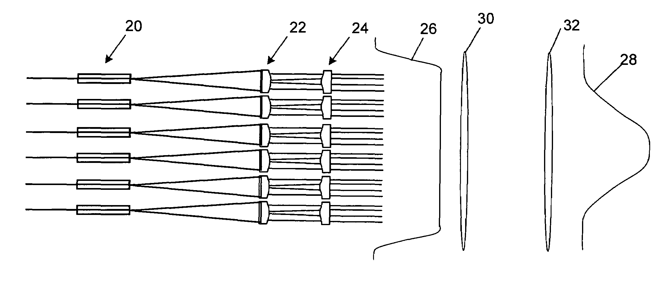
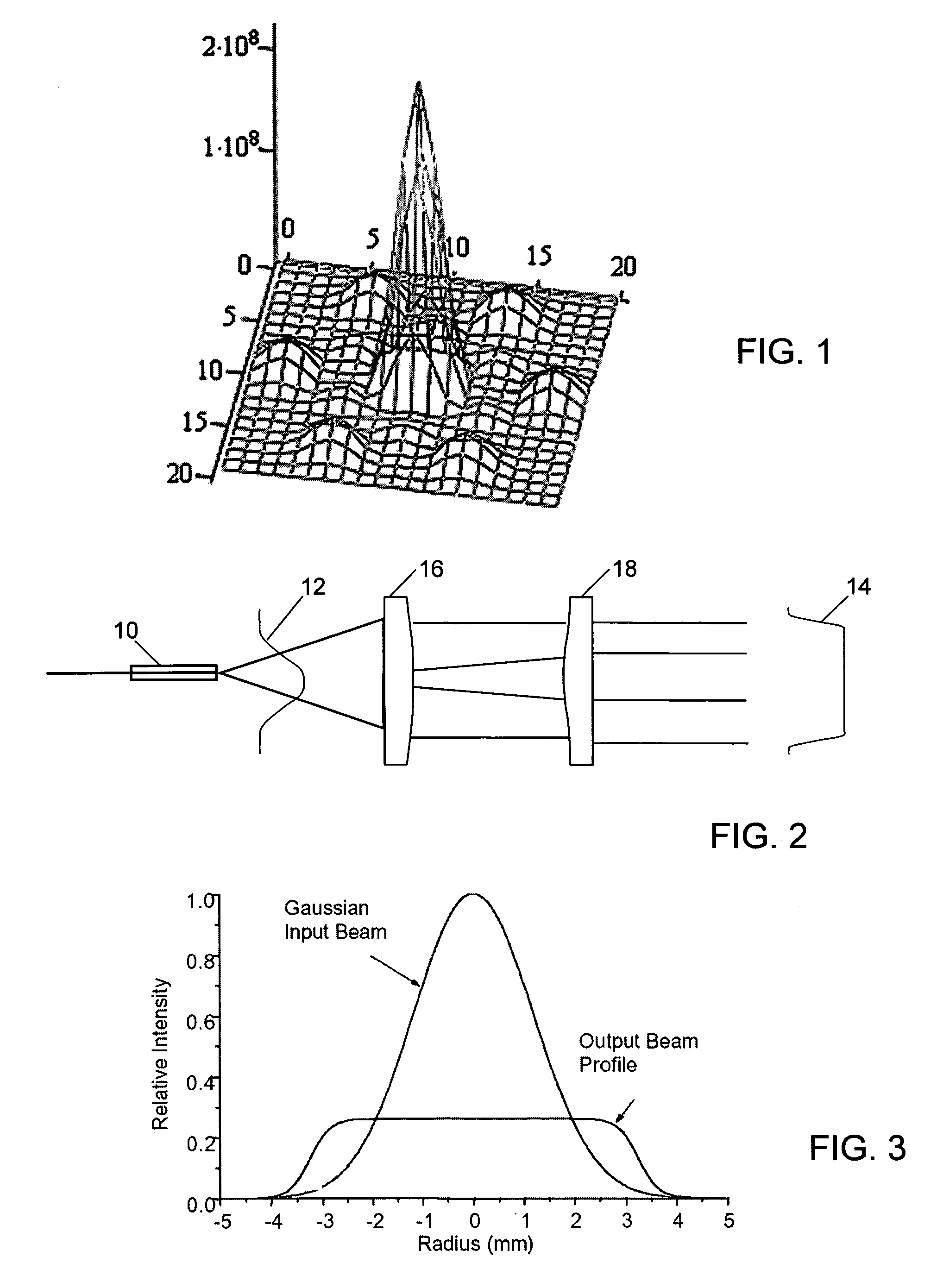
[0020]As shown in the drawings for purposes of illustration, the present invention concerns a technique for combining multiple beamlets emitted from a fiber array, in such a way as to significantly increase the encircled far field energy resulting from the radiation from the overall array. Because of diffraction effects, radiation from an array of fibers does not combine very efficiently into a single more powerful beam. Ideally, such a composite beam should have practically all of its energy confined to a central peak, preferably of Gaussian shape, but arrays typically produce a far field energy distribution in which a significant proportion of the energy falls outside the central peak. Thus the encircled energy at the far field may be as low as 60% or less. FIG. 1 shows the far field energy distribution resulting from radiation from an array of seven fibers, including one central fiber surrounded by six other fibers in a hexagonal pattern. The far field energy distribution is domi...


PUM


Abstract

Encircled far field energy is substantially increased by modifying the near field energy distribution of radiation from each fiber in an emitting array. Each beamlet output from a fiber is modified to have a generally uniform cross-sectional energy distribution, using a pair of aspheric optical elements selected for that purpose. The optical elements may be refractive or reflective. The modified beamlets combine to form a composite output beam with a generally uniform energy distribution. Preferably, the composite beam is subject to an array-wide inverse transformation to a near-Gaussian distribution, further enhancing the encircled far field energy and providing a more efficient high power laser source. Further gains in efficiency are achieved by selecting a fiber bundle pattern, lens array pattern and lens shape that together result in a high fill factor.

Description

BACKGROUND OF THE INVENTION[0001]This invention relates generally to generation of high power laser beams using arrays of optical fibers and, more particularly, to techniques for more efficiently combining multiple beams emanating from an array of fiber elements. Fiber arrays have been employed to combine the relatively small powers output from the individual fibers, to generate a composite beam of much higher power. Such arrays are well known to have a number of directed energy applications in both military and commercial contexts.[0002]When multiple sub-beams or “beamlets” from separate fibers in an array are combined to form a single composite beam, the energy distribution across the composite beam is an important factor that provides a measure of the efficiency of the beam. In the near field, close to the ends of the radiation emitting fibers, the individual beamlets retain their character as separate sources of radiation, and there will necessarily be distinct spaces between th...

Claims


Application Information

Patent Timeline
Patent Type & Authority Patents(United States)
IPC IPC(8): G02B6/32G02B3/02
CPCG02B6/32G02B6/4206G02B6/4296G02B27/58G02B6/425
Inventor BROSNAN, STEPHEN J.WICKHAM, MICHAEL G.KOMINE, HIROSHI
Owner NORTHROP GRUMMAN SYST CORP
Why Eureka
Try Eureka