Evanescently coupling light between waveguides and whispering-gallery mode optical resonators

a waveguide and optical resonator technology, applied in the field of optical systems, can solve the problems of less efficient energy transfer from the optical coupler to the optical resonator, the coupling of light between the optical resonator and the optical coupler becomes difficult, and the output peak of the wgm is broken

Inactive Publication Date: 2007-10-16
OEWAVES
View PDF53 Cites 87 Cited by
  • Summary
  • Abstract
  • Description
  • Claims
  • Application Information

AI Technical Summary

Problems solved by technology

If light from the optical coupler is over-coupled to the optical resonator, there will be broadening in the WGM output peak due to increased losses at the interface between the optical coupler and the optical resonator.
If light from the optical coupler is under-coupled to the optical resonator, there will be less efficient energy transfer from the optical coupler to the optical resonator.
If the optical coupler contacts the optical resonator, too much of the light is evanescently coupled out from the optical resonator resulting in a low Q. Also, if the optical coupler is positioned far, more than three wavelengths, from the optical resonator, coupling of light between the optical resonator and the optical coupler becomes difficult.
However, for many applications, especially where on-chip integration is desired, coupling with a prism 12 and the associated lenses (not shown) are not practical, and coupling directly from a waveguide, for example an optical fiber 10, to the optical resonator is desired as shown in FIG. 1 (see V. S. Iltchenko, X. S. Yao, and L. Maleki, Opt. Lett. 24, 723 (1999)).
Even though the use of a waveguide to couple light into an optical resonator is advantageous in that it eliminates the need for columnating and focusing optics that is commonly required for prism couplers, the precision cut of the waveguide to create the required angle is difficult to implement.
In addition, the above mentioned angle phase matching scheme is not suitable for cases in which the indices of refraction of the waveguide and the optical resonator are significantly different, for example, when the waveguide is a silicon optical fiber having a core index of refraction of 1.46 and the optical resonator is made of lithium niobate having an index of refraction of 2.06.

Method used


Image

  • Evanescently coupling light between waveguides and whispering-gallery mode optical resonators
  • Evanescently coupling light between waveguides and whispering-gallery mode optical resonators
  • Evanescently coupling light between waveguides and whispering-gallery mode optical resonators

Examples


Embodiment Construction

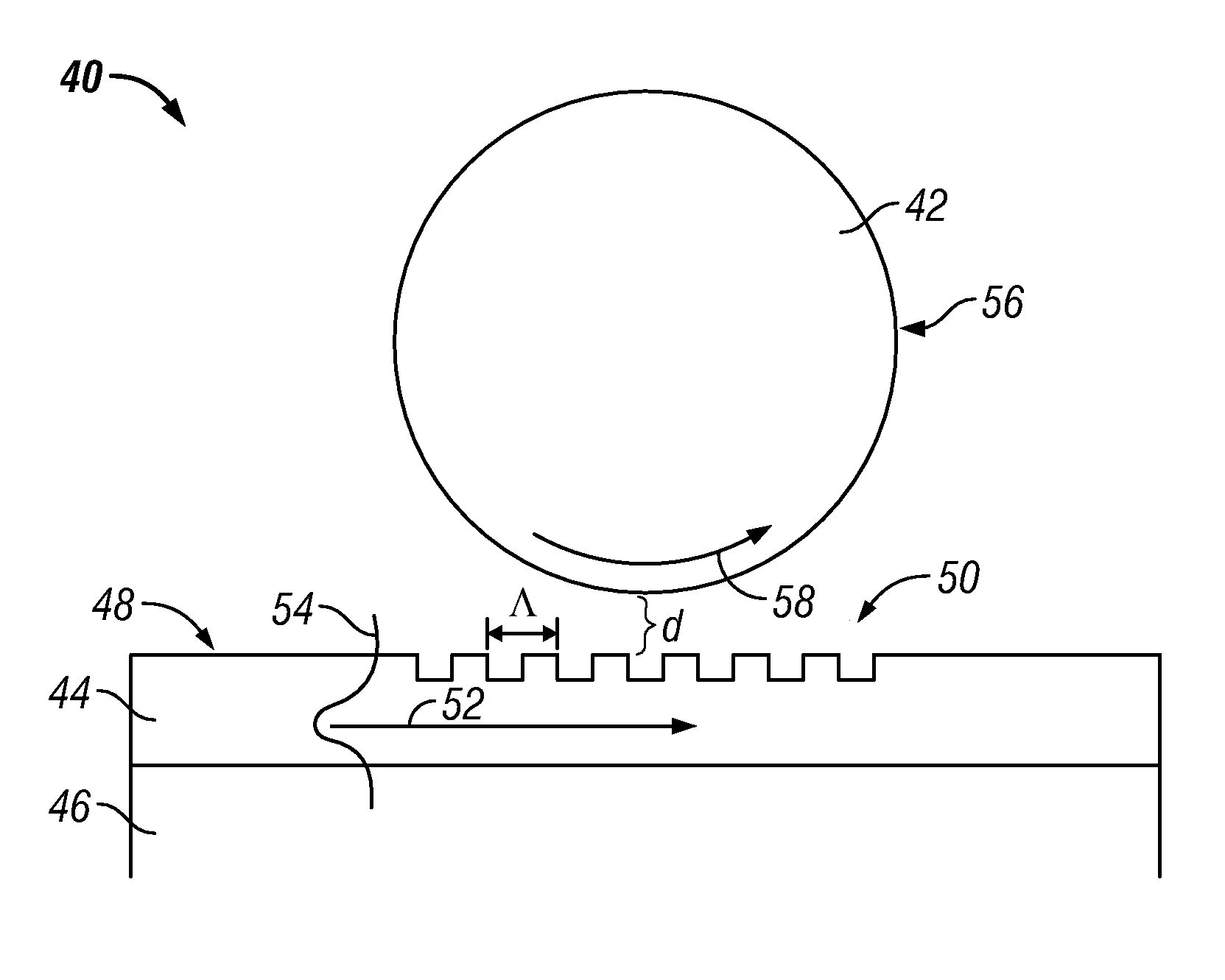
[0036]The present invention involves optical systems in which light is coupled into an optical resonator by means of an optical element having a periodic structure. The periodic structure facilitates the coupling of light from the optical element into the optical resonator. One embodiment of the present invention is a system that includes an optical resonator and a waveguide. The waveguide has a periodic structure adjacent to the optical resonator. Light propagates through the waveguide, interacts with the periodic structure, and couples from the waveguide into the optical resonator.

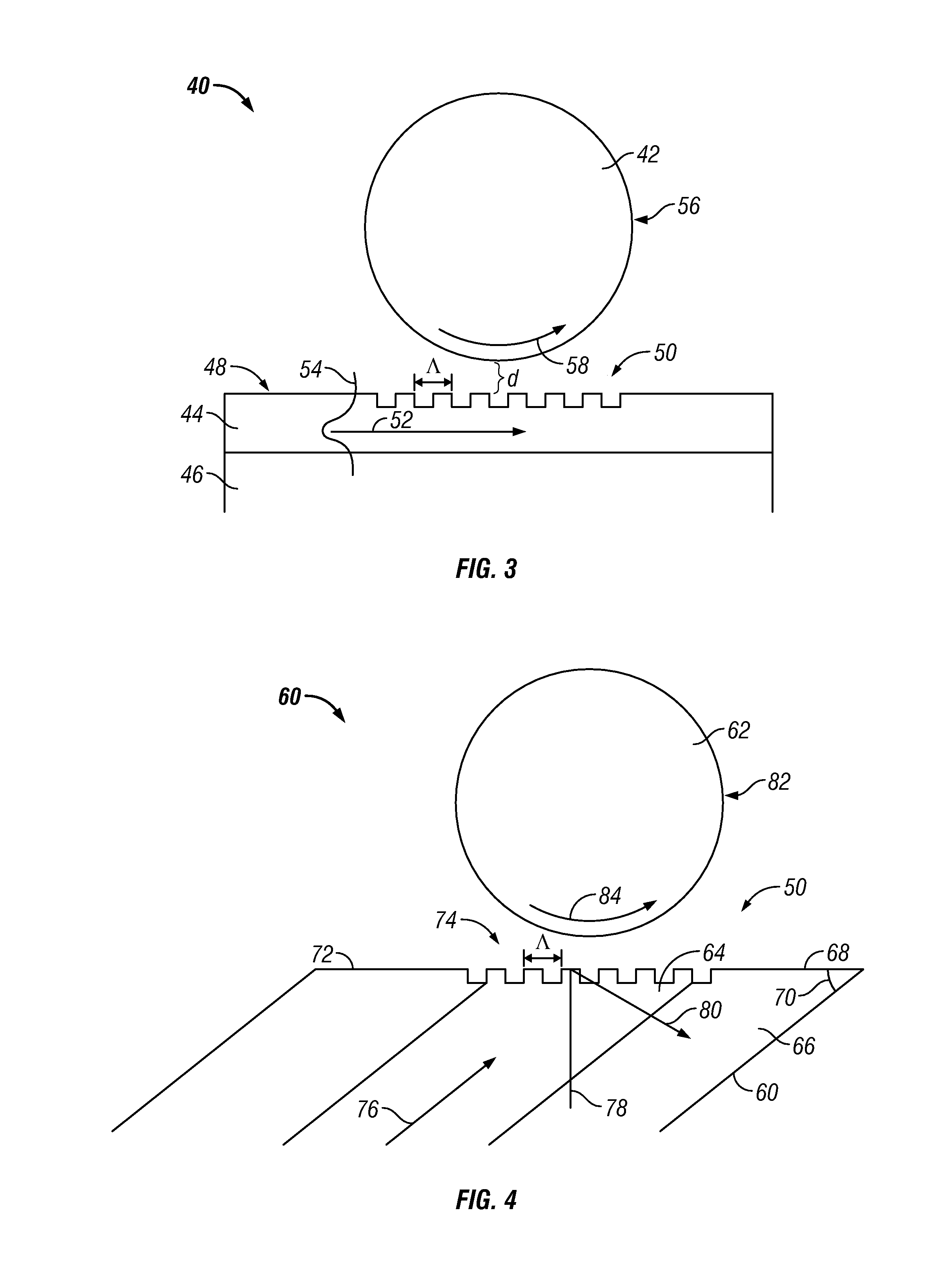
[0037]Another embodiment of the present invention is a system that includes an optical resonator and an optical coupler. The optical coupler has an optical coupler surface with a periodic structure located adjacent to the optical resonator. Light propagates through the optical coupler, interacts with the periodic structure, and couples from the optical coupler into the optical resonator.

[0038]Another emb...


PUM


Abstract

An exemplary embodiment of the present invention described and shown in the specification and drawings is a system including an optical resonator and an optical element having a periodic structure for coupling of light into the optical resonator.

Description

CROSS-REFERENCE TO RELATED APPLICATION[0001]The present application claims priority under 35 U.S.C. § 119(e) to U.S. Provisional Application No. 60 / 307,777, filed on Jul. 25, 2001, which is expressly incorporated by reference as though fully set forth herein.FIELD OF THE INVENTION[0002]The present invention relates to optical systems, and in particular, to a scheme for coupling light between waveguides and whispering-gallery mode optical resonators.BACKGROUND OF THE INVENTION[0003]Optical resonators are exemplary electro-optical devices that are often small in size, having diameters on the order of millimeters, and may be used in many optical system applications, including optical sensors for biological and chemical compounds, electro-optical oscillators and modulators, and tunable optical filters. The optical resonators are curved optical waveguides, for example, a cylinder, a sphere, or a toroid within which light is internally reflected at the inner surface of the optical resonat...

Claims


Application Information

Patent Timeline
Patent Type & Authority Patents(United States)
IPC IPC(8): G02B6/26G02B6/42
CPCB82Y20/00G02B6/12007G02B6/29317G02B6/29341G02B6/1225G02B6/29395
Inventor MALEKI, LUTFOLLAHIITCHENKO, VLADIMIR S.
Owner OEWAVES
Why Eureka
Try Eureka