Externally-loaded weighted random test pattern compression

a test pattern and weighted random technology, applied in the field of compression of test patterns, can solve the problems of increasing test application time and test cost, increasing the size of scan test pattern sets, and increasing the size of test application memory, so as to achieve the effect of greater compression ra

Inactive Publication Date: 2007-10-16
NEC CORP
View PDF2 Cites 13 Cited by
  • Summary
  • Abstract
  • Description
  • Claims
  • Application Information

AI Technical Summary

Benefits of technology

[0005]The present invention is directed to a logic testing architecture that is capable of reusing seeds to generate multiple test patterns. In accordance with an embodiment of the present invention, the decompression engine comprises three pseudo-random pattern generators, such as linear feedback shift registers. Two out of the three pseudo-random pattern generators are seeded while the third pseudo-random pattern generator can be free running. The three pseudo-random pattern generators have outputs which are combined so as to generate values which are inserted into one or more scan chains. For example, the three pseudo-random pattern generators can be combined using a selection circuit which selects values for the scan chain from either a seeded pseudo-random pattern generator or the free running pseudo-random pattern generator, based on a value from the other seeded pseudo-random pattern generator. The selection circuit can be readily implemented, for example, using a multiplexer or a circuit comprising an AND gate and an OR gate.

Problems solved by technology

Unfortunately, the sizes of scan test patterns for today's large designs can be even larger than the sizes of typical tester memory.
This necessitates multiple loading of test patterns during a test application and, in turn, increases test application time and test cost.
The oversized test pattern set problem is even more severe in delay testing, which has become a necessary test procedure for deep-sub micron chips.
This can result in high routing overhead.
Synopsys DBIST / XDBIST does generate a fixed number of test patterns from each seed; however, the additional generated test patterns are not guaranteed to detect any new faults, thereby resulting in disadvantageous increases in test application time.

Method used


Image

  • Externally-loaded weighted random test pattern compression
  • Externally-loaded weighted random test pattern compression
  • Externally-loaded weighted random test pattern compression

Examples


Embodiment Construction

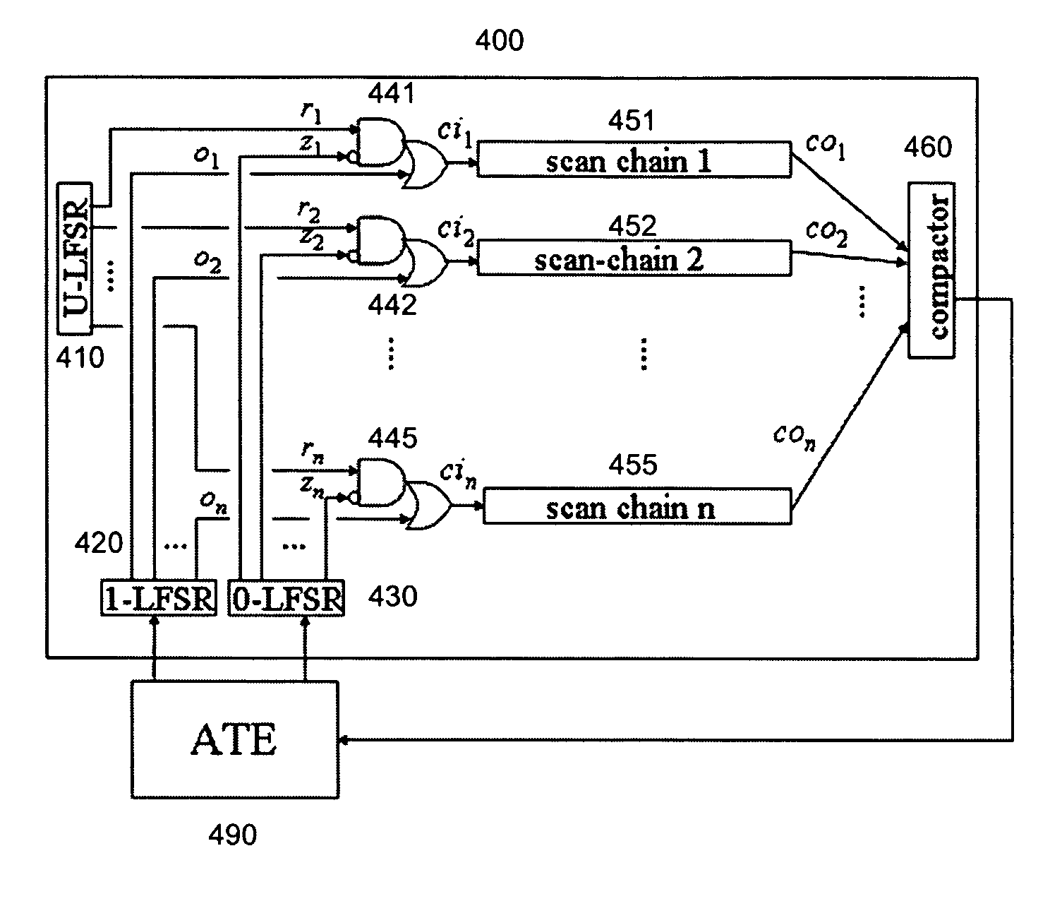
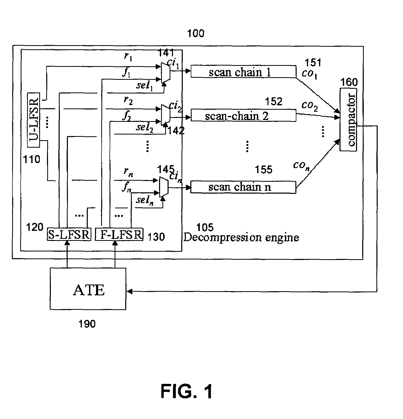
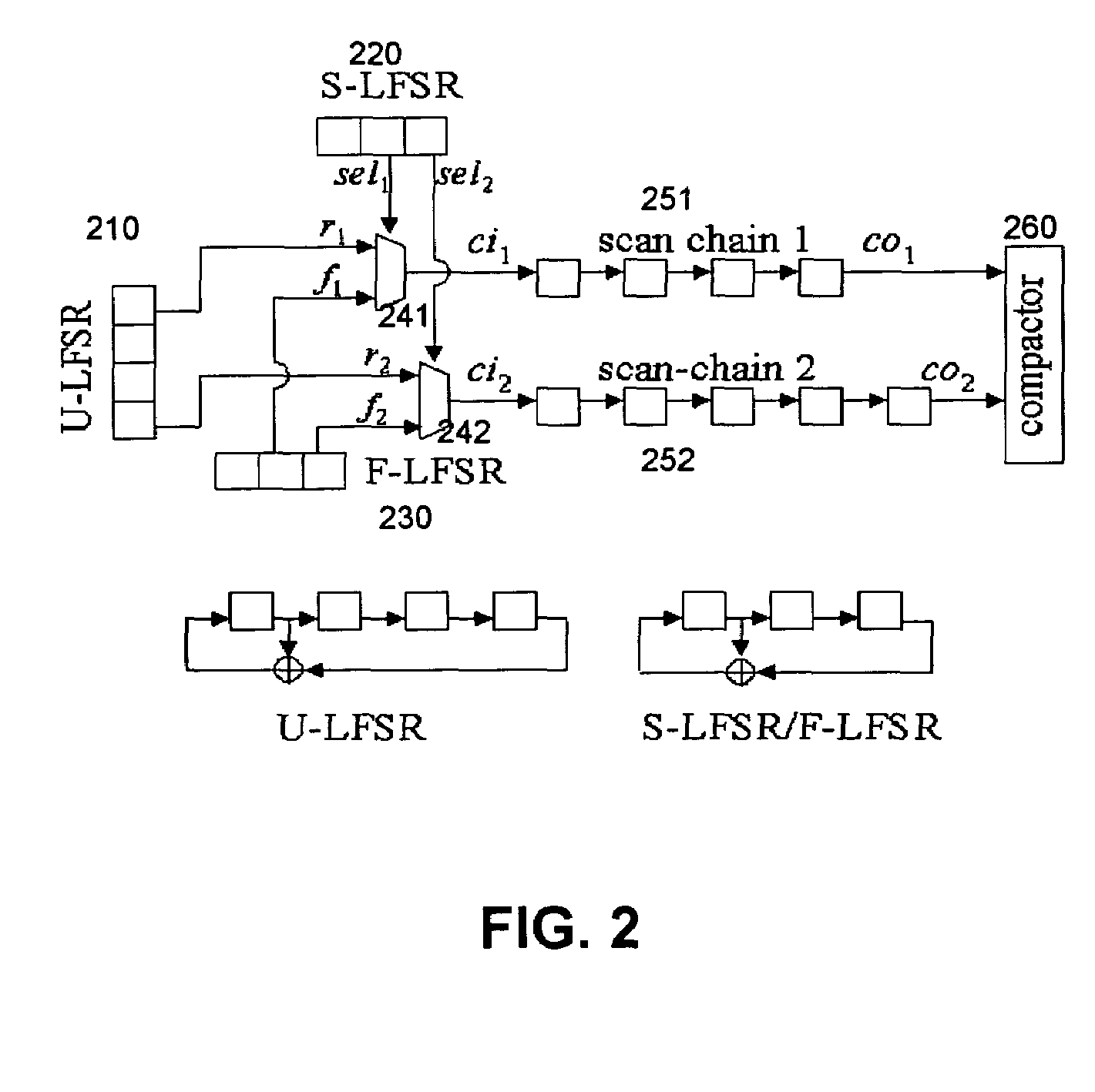
[0015]FIG. 1 is a diagram illustrating a decompression architecture 100 in accordance with an embodiment of the present invention. The decompression engine 105 comprises three linear feedback shift registers (LFSRs), namely, U-LFSR 110, F-LFSR 120, and S-LFSR 130, and n multiplexers (2 to 1 multiplexers) 141, 142, . . . 145, where n is the number of scan chains 151, 152, . . . 155 in the circuit. The U-LFSR 110 is a free running LFSR and generates pure pseudo-random pattern sequences. One input of each multiplexer connects to an output of the U-LFSR 110 and the other input connects to an output of the F-LFSR 120. The F-LFSR 120 and the S-LFSR 130 are re-loadable, i.e. a new seed can be loaded into these LFSRs from external automatic test equipment (ATE) 190 whenever it is necessary to change test pattern sequences. Outputs of the S-LFSR 120 drive select inputs of the n multiplexers; if the select input of a multiplexer is set to a 0 at a scan shift cycle, a random value, which is ge...


PUM


Abstract

The present invention is directed to a logic testing architecture with an improved decompression engine and a method of decompressing scan chains for testing logic circuits.

Description

BACKGROUND OF THE INVENTION[0001]The present invention is related to testing of logic circuit designs, in particular in the context of compression of test patterns for logic testing.[0002]Testing of complicated digital logic circuits requires the generation of large test patterns. Unfortunately, the sizes of scan test patterns for today's large designs can be even larger than the sizes of typical tester memory. This necessitates multiple loading of test patterns during a test application and, in turn, increases test application time and test cost. The oversized test pattern set problem is even more severe in delay testing, which has become a necessary test procedure for deep-sub micron chips. Delay test set sizes are often significantly larger than memory capacities of inexpensive testers. Test set sizes and test application times are major factors that determine the test cost of an integrated circuit.[0003]One technique for addressing the issue is to compress the test data. It has ...

Claims


Application Information

Patent Timeline
Patent Type & Authority Patents(United States)
IPC IPC(8): G01R31/28G06F17/50
CPCG01R31/318335G01R31/31921G01R31/318385
Inventor WANG, SEONGMOONCHAKRADHAR, SRIMAT T.
Owner NEC CORP
Why Eureka
Try Eureka