Milling device for floors, rock, excavated material or other material

a technology of excavated material and milling device, which is applied in the direction of cutting machines, grain treatment, ways, etc., can solve the problem of not being able to easily break through the solid top layer

a technology of excavated material and milling device, which is applied in the direction of cutting machines, grain treatment, ways, etc., can solve the problem of not being able to easily break through the solid top layer

US7284345B2Inactive Publication Date: 2007-10-23SCHENK JURGEN

Image

  • Milling device for floors, rock, excavated material or other material
  • Milling device for floors, rock, excavated material or other material
  • Milling device for floors, rock, excavated material or other material

Examples


Embodiment Construction

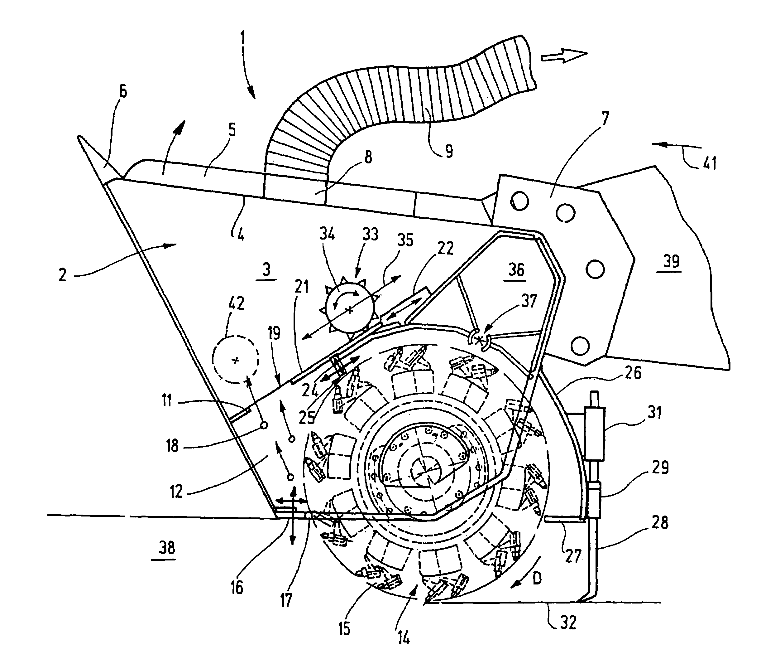
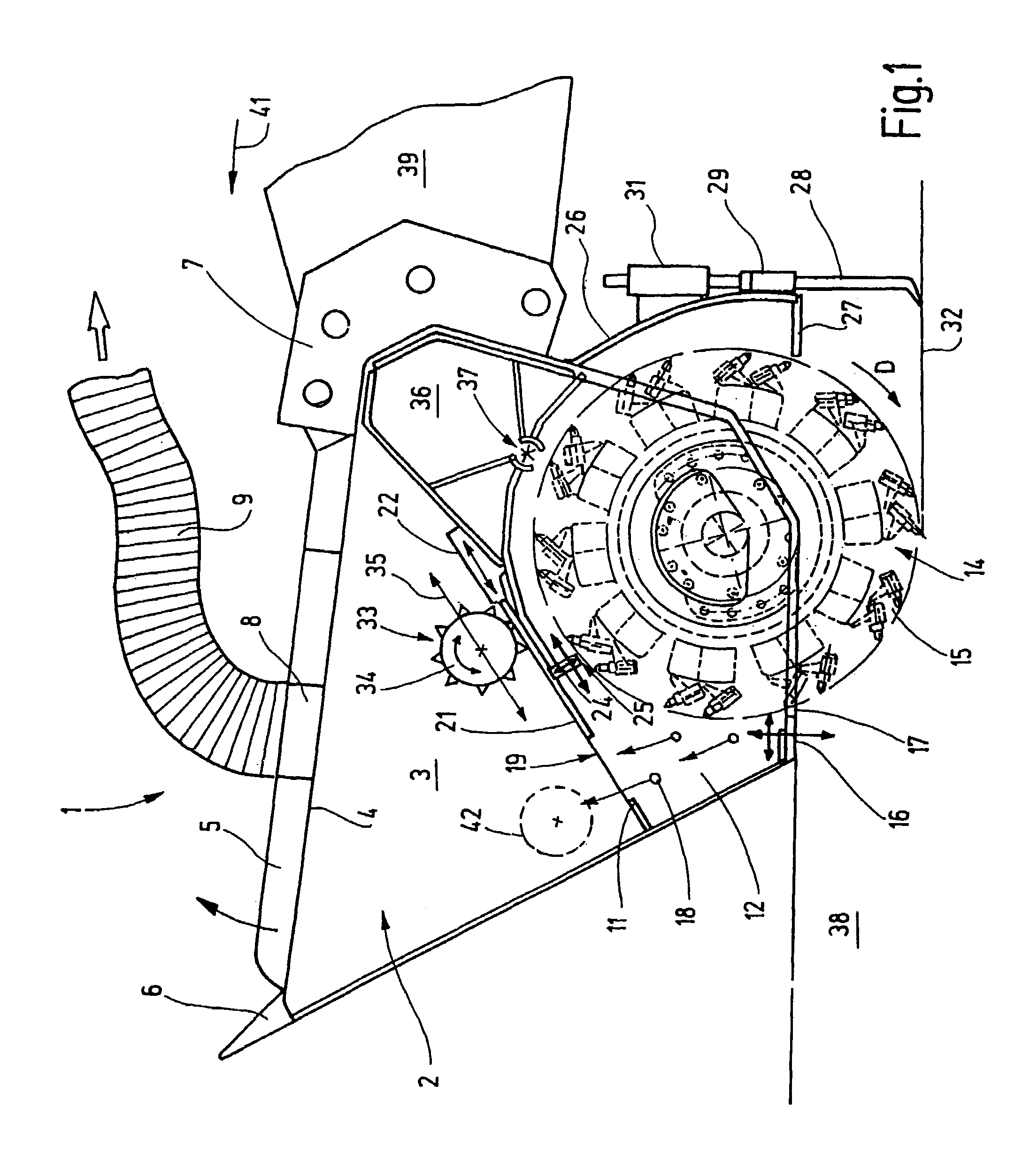
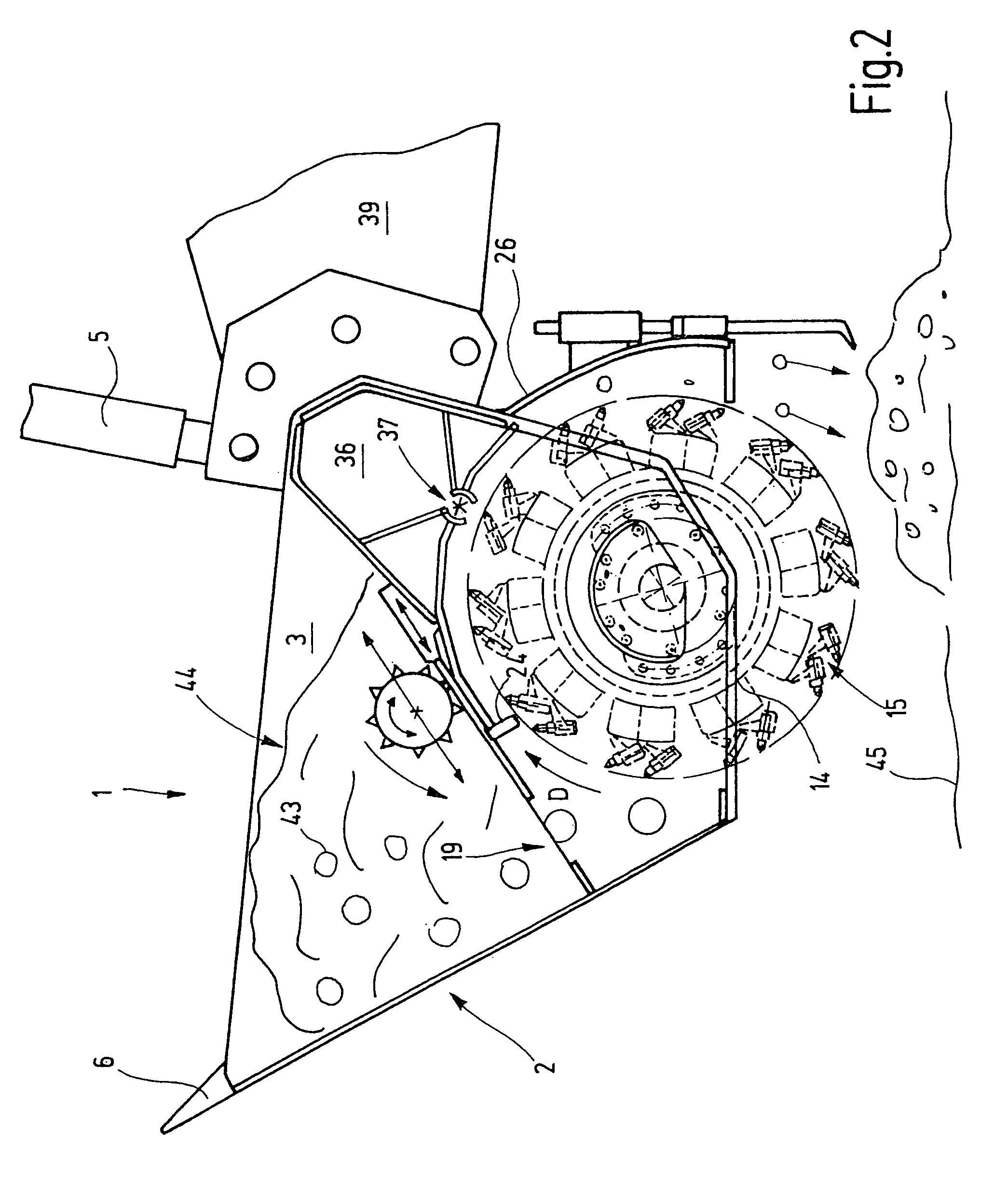
[0031]In FIG. 1, a milling apparatus 1 is shown, which can for instance replace an excavator bucket or the bucket of a wheel loader, or can be guided by some other kind of device. The milling apparatus 1 has a bucket 2, which encloses a receiving chamber 3. At the top of the bucket 2, the receiving chamber has a receiving opening 4, which is closed by a lid 5. Teeth 6 can be embodied on the edge of the receiving opening 4. The lid 5 is pivotably supported on a holder 7. It can be provided with a suction opening 8, to which an suction extractor is connected via a suction line 9. The suction extractor can be supported by the device that carries the milling apparatus 1, or it can be set up separately.

[0032]In the bucket 2, a milling chamber 12 in which a milling rotor 14 is rotatably supported is partitioned off via a partition 11. The milling rotor is equipped with tools 15, such as hard metal chisels, which serve to comminute the material and mix it and are inclined in the direction ...


PUM


Abstract

The milling apparatus (1) has a bucket with a receiving chamber and has a milling unit with a milling rotor (14). The receiving chamber has a receiving opening (4) and is embodied as a bucket (2). On the bottom of the bucket (2), a through opening (19) is provided, which leads into a milling chamber (12). The milling rotor (14) can move material both into the receiving chamber and out of it again. To achieve both modes of operation, in a first embodiment a drive mechanism rotating in a predetermined direction (D) is provided; a beating arm (16) is associated with the first mode of operation, and a further beating arm (24) is associated with the second mode of operation. In another embodiment, which makes do with a single beating arm (16), the milling unit (54) can be operated in two different working positions via a turner. The positions differ from one another by a 180° rotation about a vertical axis that is perpendicular to the axis of rotation of the milling rotor (14).

Description

BACKGROUND OF THE INVENTION[0001]1. Field of Invention[0002]The invention relates to a milling apparatus for comminuting soil, rock or other material.[0003]2. Description of the Related Art[0004]For excavating soil, suitable digging devices such as excavators are known. However, these are not readily capable of breaking through solid top layers, such as concrete or asphalt, or picking up rock at depth, or mixing the excavated material. Combined digging, mixing and milling equipment has therefore been developed. One such system is known for instance from German Patent Disclosure DE 199 07 430 A1. This system has an excavator bucket that is provided with a miller on its back side. The miller is accommodated in a milling chamber and protrudes from it. Between the milling chamber and the receiving chamber of the excavator bucket, there is an opening, embodied for instance in the form of a sieve. Thus granular material that occurs in the milling process can be collected in the excavator ...

Claims


Application Information

Patent Timeline
23 Oct 2007
Publication
US7284345B2
IPC
E02F3/96; E01C21/00; E02F3/36; E01C23/088; E01C23/12; E02F3/40; E02F5/08
CPC
E01C21/00; E01C23/088; E02F7/06; E02F3/407; E01C2301/50
Inventors
SCHENK, JURGEN