System and method for hydronic space heating with electrical power generation

a hydronic space heating and electrical power generation technology, applied in the field of cogeneration of space/water heat and electrical power, can solve the problems of large fraction of fuel energy normally dispersed as waste heat, no widespread use of small-scale cogeneration, and little attention to how such small-scale power generation technologies could be practically integrated, so as to maximize the run time, minimize the starting and stopping of the electric generator, and maximize the effect of electric power

Active Publication Date: 2007-10-23
CLIMATE ENERGY
View PDF50 Cites 67 Cited by
  • Summary
  • Abstract
  • Description
  • Claims
  • Application Information

AI Technical Summary

Benefits of technology

[0013]In an illustrative embodiment, the various heating zones in the building are operated in a manner by a control system such that the heat produced by the generator is optimally applied to the different zones to maintain the desired space temperature in each zone while simultaneously maximizing the run time and minimizing the starting and stopping of the electric generator. A control module is provided to regulate these and other relationships between operational components so that, during heating, the utilization of the power generator as the heat source is maximized, the power consumption of the heating system components is minimized, the use of the auxiliary heating hydronic boiler is minimized, all components are maintained within their operational temperature limits, and the thermal comfort is maintained in the different heating zones in the building.
[0014]An outdoor temperature sensor can be beneficially used, along with a zone operation control strategy, to improve the heat demand anticipation of the system and further maximize the use of the electric generator as a heat source. Domestic potable water heating can be provided by exchange of heat from the hydronic water circuit through a heat exchanger, with heat produced preferably by the engine-generator and then, if needed, by the auxiliary hydronic boiler. The auxiliary boiler and generator combinations can share combustion air intake ductwork and combustion product vents as well as condensate drains. The engine electric generator can be mounted indoors or outdoors. During periods of electrical grid power failure and when heat is not needed, the system provides for the operation of the electric generator for emergency power. Similarly, when the generator must take over for the power grid in the event of an outage, it may be run by the control module at a higher electric power output level / speed and excess heat may be dissipated if necessary.

Problems solved by technology

All forms of electric power generation at large remotely located generating plants result in a large fraction of the fuel energy being normally dissipated as waste heat.
However, there is as yet no widespread use of small-scale cogeneration.
To date, little attention has been paid specifically as to how such small-scale power generation technologies could be practically integrated into hydronic (i.e. forced hot water) system.
However, there are important practical technical considerations and limitations with respect to use and integration of such candidate electric generator technologies so as to limit the simple attachment of such generators to hydronic heating systems.
While attempts to produce a small-scale cogeneration system have been made, these either do not interface with commonly used residential and small commercial hydronic heating systems, or are impractical to employ in a “real-world” application at the residential and small commercial level.
In particular, the specific issues associated with operation with a multi-zone residential and commercial hydronic heating systems have not been addressed.
This system also works effectively where relatively low hydronic heating water temperatures (e.g. potable water temperatures) are permissible, but this system of limited advantage in typical North American applications that tend to require relatively high hydronic water temperatures.
Also, this prior art system requires storage tank and heat exchanger assemblies not commonly produced in North America.
In addition the above-described prior art design does also not take into account the “net metering” utility interconnection that is available in the United States, and that provides for maximizing the economic advantages of cogeneration under the prevailing operational situation.

Method used


Image

  • System and method for hydronic space heating with electrical power generation
  • System and method for hydronic space heating with electrical power generation
  • System and method for hydronic space heating with electrical power generation

Examples


Embodiment Construction

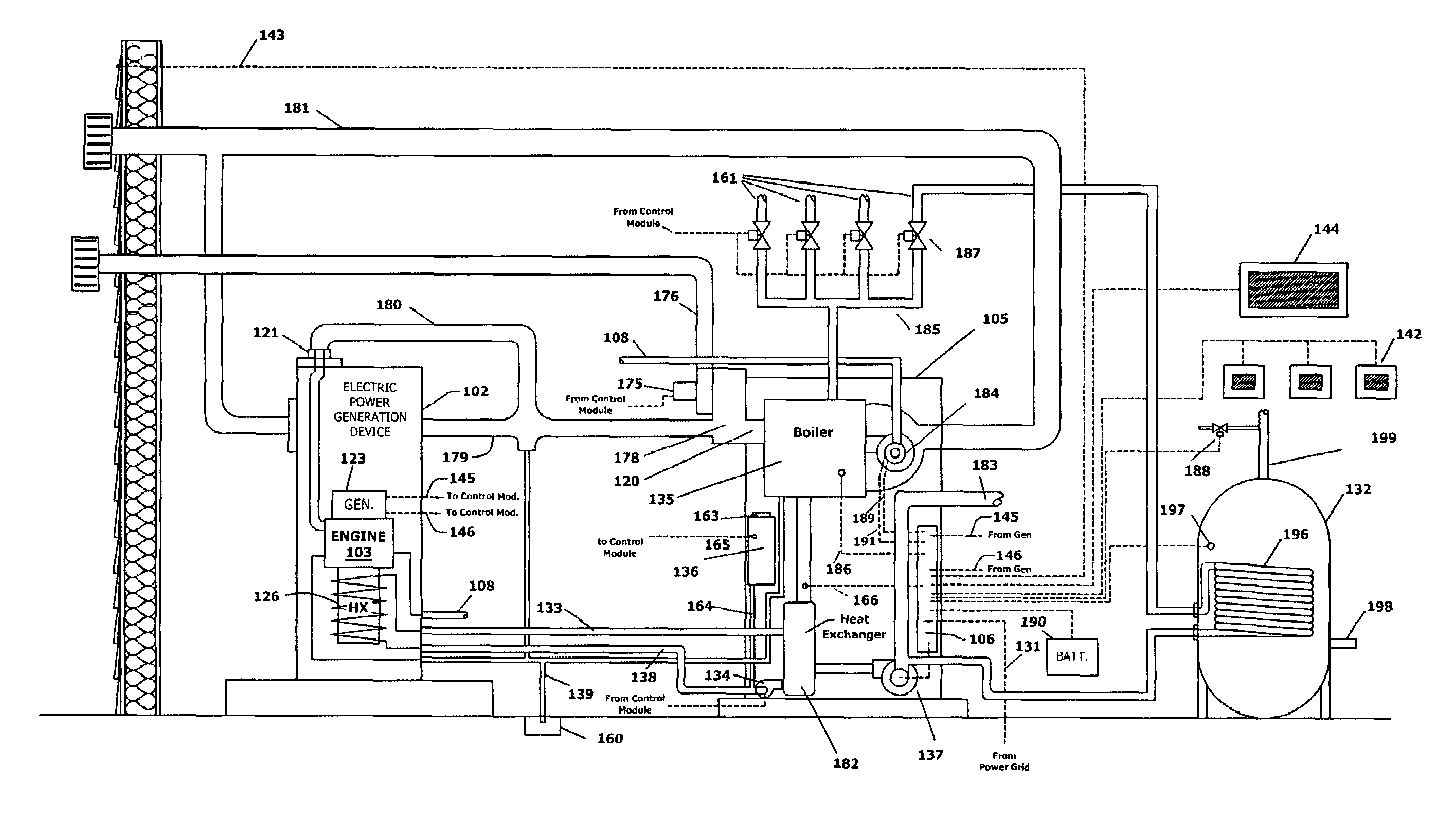
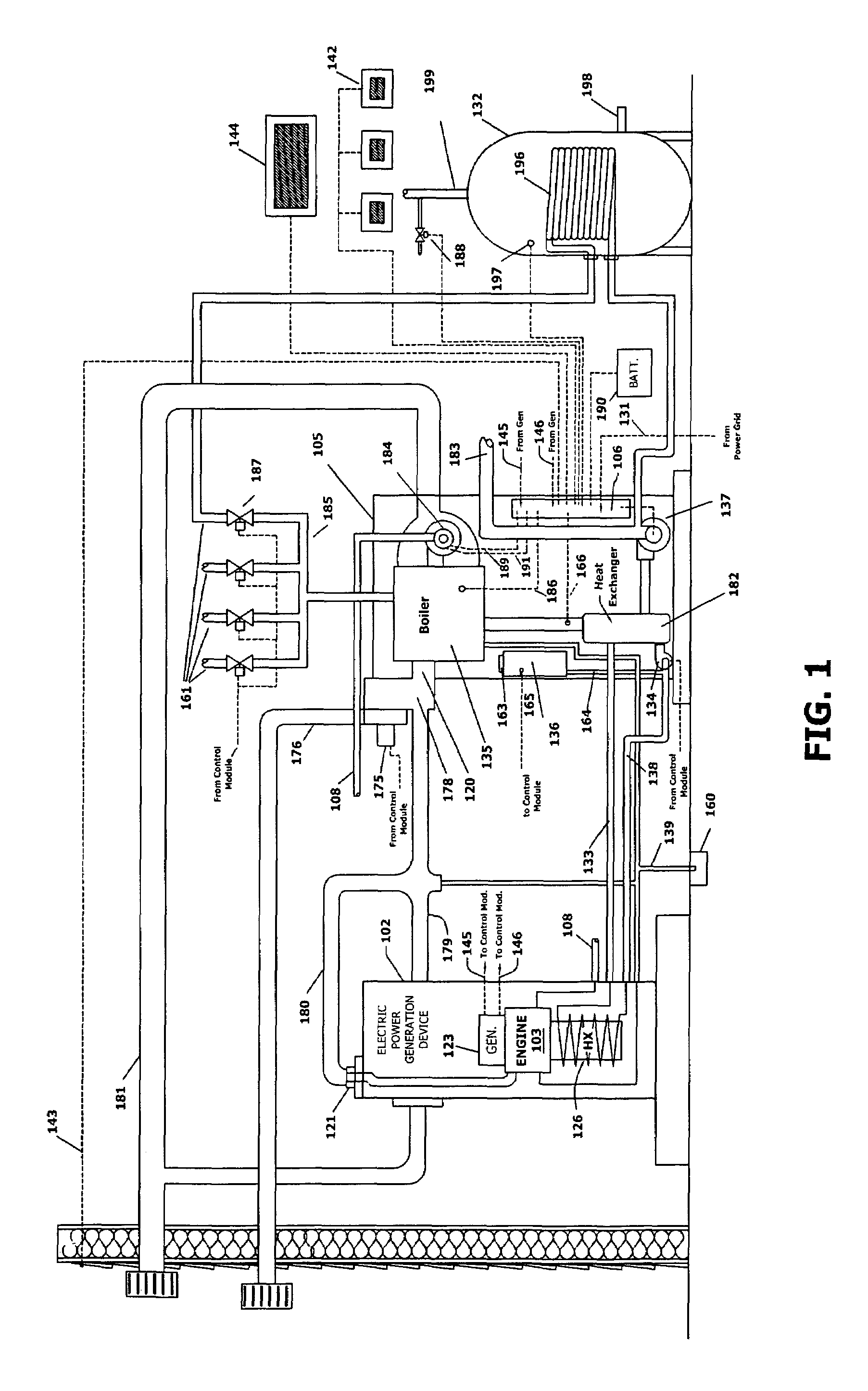
[0020]FIG. 1 illustrates a hydronic heating micro-CHP system installed in a typical North American residential application according to an embodiment of this invention. This system is related to that described in the incorporated-by-reference U.S. patent application Ser. No. 10 / 704,358, which was filed on Nov. 7, 2003, by Eric C, Guyer for a SYSTEM AND METHOD FOR WARM AIR SPACE HEATING WITH ELECTRICAL POWER GENERATION. Unless different elements and methods are described, it can be assumed, where appropriate that elements and methods described in the above incorporated-by-reference U.S. patent application Ser. No. 10 / 704,358 can be employed in connection with the teachings of this invention.

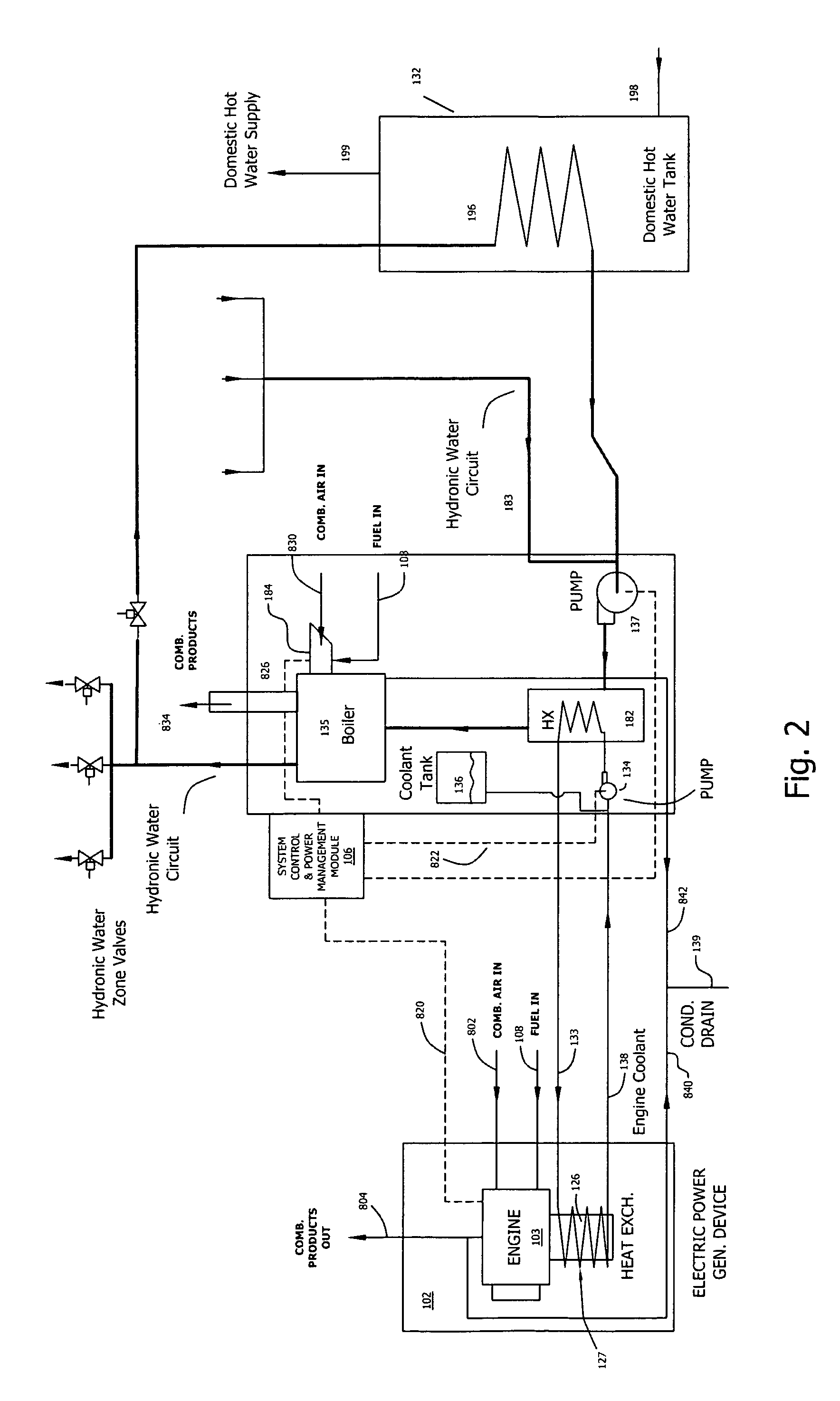
[0021]FIG. 1 is best understood by recognition that there are three separate liquid fluid circuits in the system. Briefly, these are the “engine coolant” circuit, the “hydronic water” circuit, and the “domestic (potable) hot water” circuit. For clarity, the terms, “engine coolant,”“hydronic water,...


PUM


Abstract

This invention provides a system and method for cogeneration of electric power and building heat that efficiently interfaces a liquid-cooled electric power generator with a multi-zone forced hot water (hydronic) space heating system. The system and method utilizes an electric generator with an electric output capacity (kW) that is near the time-averaged electric power consumption rate for the building and with a heat generation capacity that is useful for meeting building heating needs. This generator is operated as the priority source of heat for the building, but normally only when there is a demand for heat in building, with the intent of running the generator for long periods of time and generating a total amount of electric energy (kWhs) that is significant in comparison to the total electric energy consumption of the building over time. The actual onsite time-variable power demand (kW) is met by a combination of the cogenerated electric power produced on site and quantities of electric power from the public electric power grid or another external power source. Hence, useful electric power is generated on site as a by-product of the required generation of heat for space or water heating. The generator is run at a speed / operating condition that is appropriate to maintaining a long operational life.

Description

CROSS-REFERENCE TO RELATED APPLICATIONS[0001]The present application is a continuation-in-part of commonly assigned U.S. patent application Ser. No. 10 / 704,358, which was filed on Nov. 7, 2003 now U.S. Pat. No. 7,040,544, by Eric C. Guyer for a SYSTEM AND METHOD FOR WARM AIR SPACE HEATING WITH ELECTRICAL POWER GENERATION, and is hereby incorporated by reference.BACKGROUND OF THE INVENTION[0002]1. Field of the Invention[0003]This invention relates to the cogeneration of space / water heat and electrical power.[0004]2. Background Information[0005]In most regions of North America, space heating of buildings is a necessity for some portion of the year to maintain thermal comfort. Buildings are space-heated in a variety of ways, with one of them being so-called forced hot water or “hydronic” heating, using a pump to recirculate water in a closed system through a “boiler” for heating, through pipes, and to a variety of space heating devices such as baseboard fin-tube radiators, radiant pane...

Claims


Application Information

Patent Timeline
Patent Type & Authority Patents(United States)
IPC IPC(8): F24D5/00F02B63/04F02G1/043F02G5/02F02G5/04F24D3/08F24D5/02F24D12/02F24D18/00
CPCF24D5/02F24D12/02F24D3/08F24D2200/26Y02T10/166F24H2240/06Y02B30/14Y02E20/14F24H2240/00Y02B30/00Y02T10/12F24D2101/30F24D18/00F24D2101/10F24D2101/70F24D2105/00F24D2103/13F24D2101/60F24D2103/20F24D2101/80
Inventor GUYER, ERIC C.
Owner CLIMATE ENERGY
Why Eureka
Try Eureka