
Flexographic proofing tools and methods

a technology of flexographic printing and proofing equipment, which is applied in the field of flexographic printing, can solve the problems of high cost of printing press, non-productive time used for printing press test, and high cost of modern printing press

Inactive Publication Date: 2013-01-03
PROBITY ENG
View PDF5 Cites 4 Cited by
  • Summary
  • Abstract
  • Description
  • Claims
  • Application Information

AI Technical Summary

Benefits of technology

The invention is a device and method for preparing and optimizing printing plates for printing presses. It includes a mechanism for adjusting the nip between the transfer roll and the drive roller of the proofing machine to prevent the nip distance from being smaller than a set value. The method involves preparing a printing plate for the printing press simultaneously or in parallel with a printing plate for a proofing device, which is mounted on the proofing device, and adjusting the parameters of the printing plate to minimize ink transfer and achieve optimal performance on the printing press. This helps to minimize printing press downtime and maximize printing press run time. The technical effects of this invention include improved printing plate performance and reduced printing press downtime.

Problems solved by technology

Printing plates can be and often are tested on the printing press but the expense of doing so is high.
Modern printing presses are expensive.
Any time that is used to test on the press is non productive time and cannot be used for profitable production.
A printing press requires considerable time for setup and cleanup in addition to the time that is used in a test run.
In addition, modern printing presses operate at high speed and can consume large quantities of ink and substrate quickly adding to the expense of testing.
While current proofing techniques are helpful in preparing for production printing press runs they are not adequate to predict the performance of the printing press.
1. An anilox which transfers metered ink from the doctor blade to the transfer roll or photopolymer plate.
2. A doctor blade located near the top of the anilox and positioned with its edge trailing (creating wiping action). This wiping action is necessary because ink needs to be forced into the anilox before metering it. So a trailing edge anilox services two purposes, forcing ink into anilox and metering it level to the anilox surface. These two actions compromise each others' ability to perform. The wiping action of the trailing blade tends to lift the doctor blade, allowing non-metered ink to pass. This non-metered amount of ink reduces accuracy of ink application and reduces the quality and consistency of the resulting proof.
3. An ink transfer roll that receives ink from the anilox and applies an ink sample to the substrate.

Method used


Image

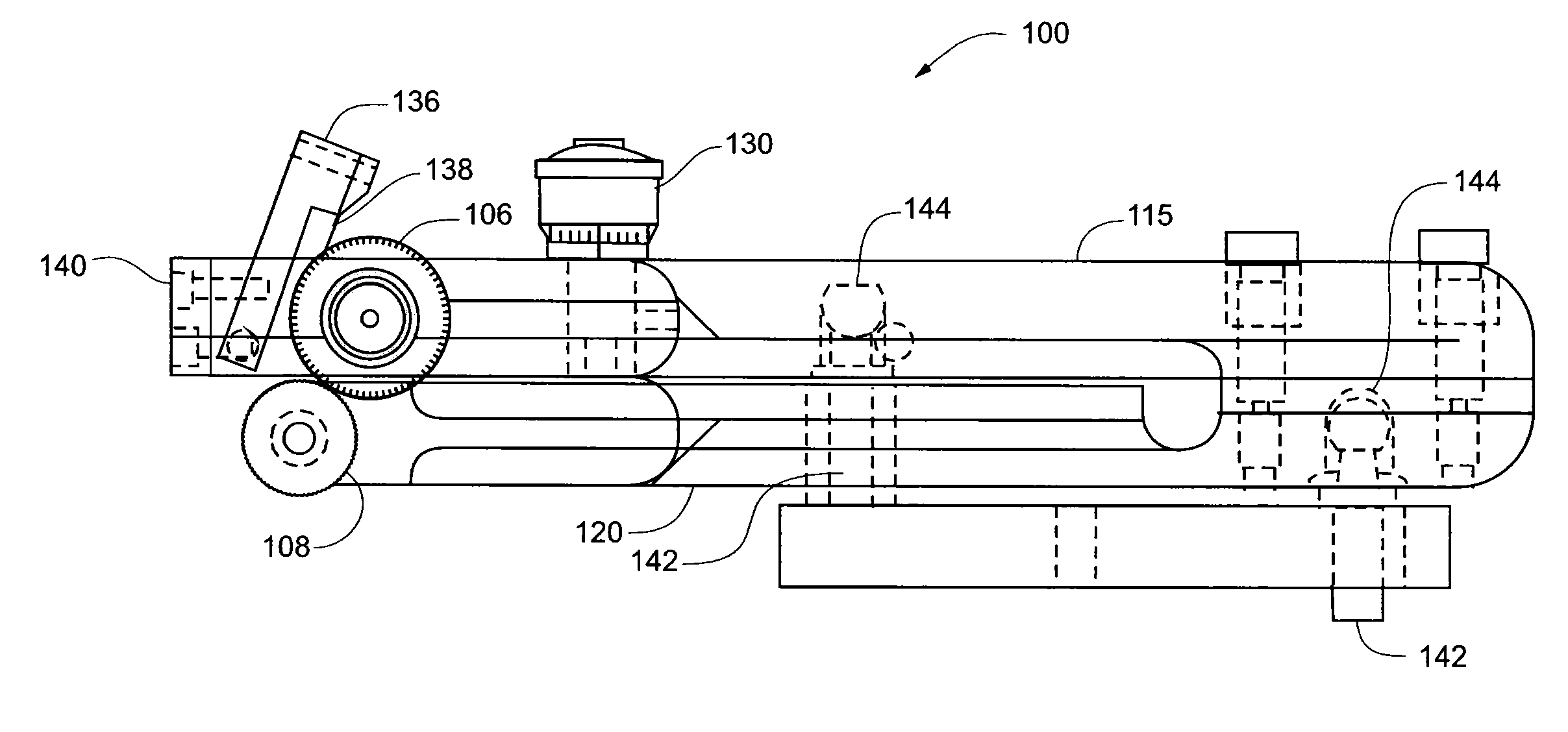
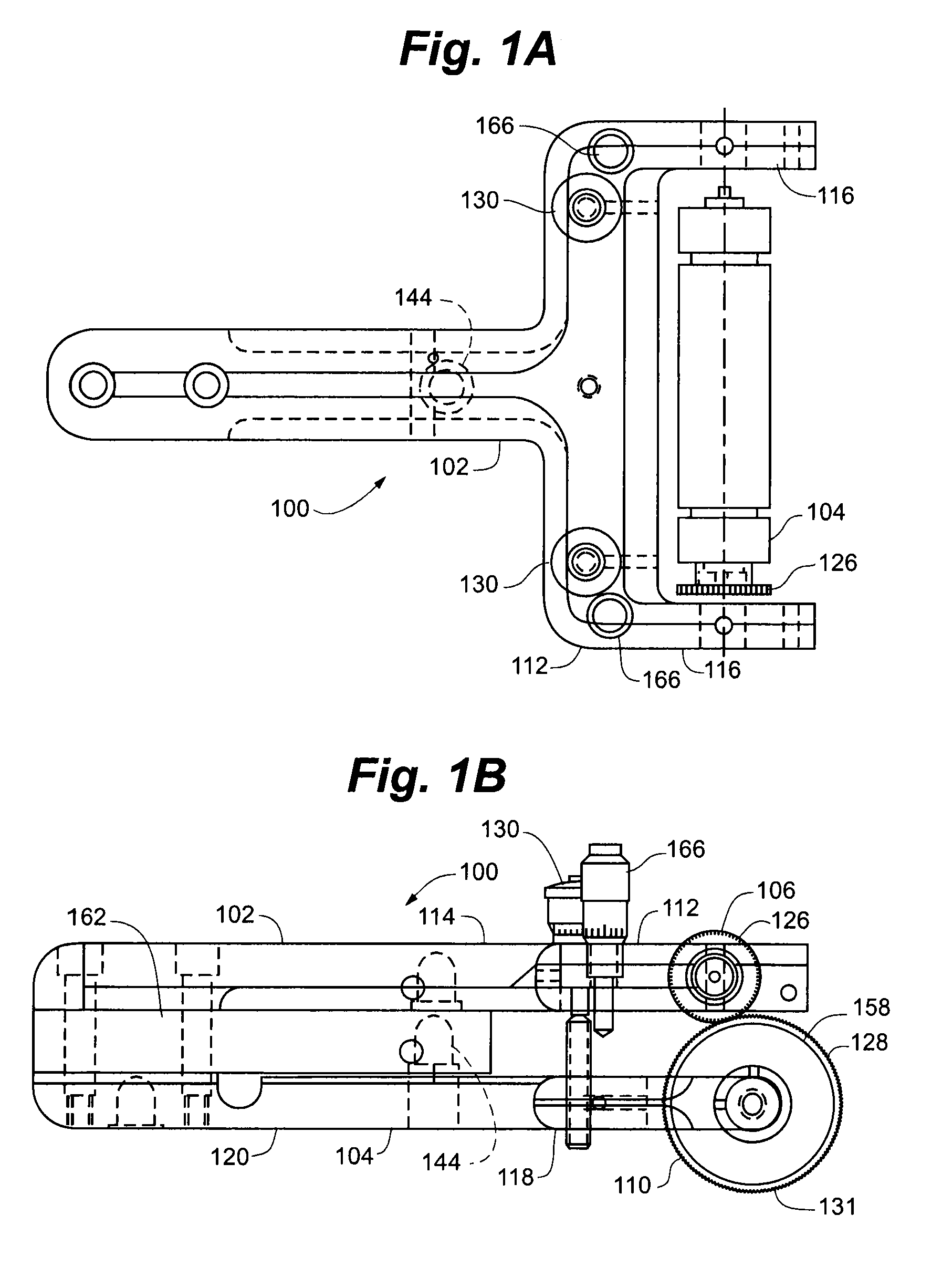
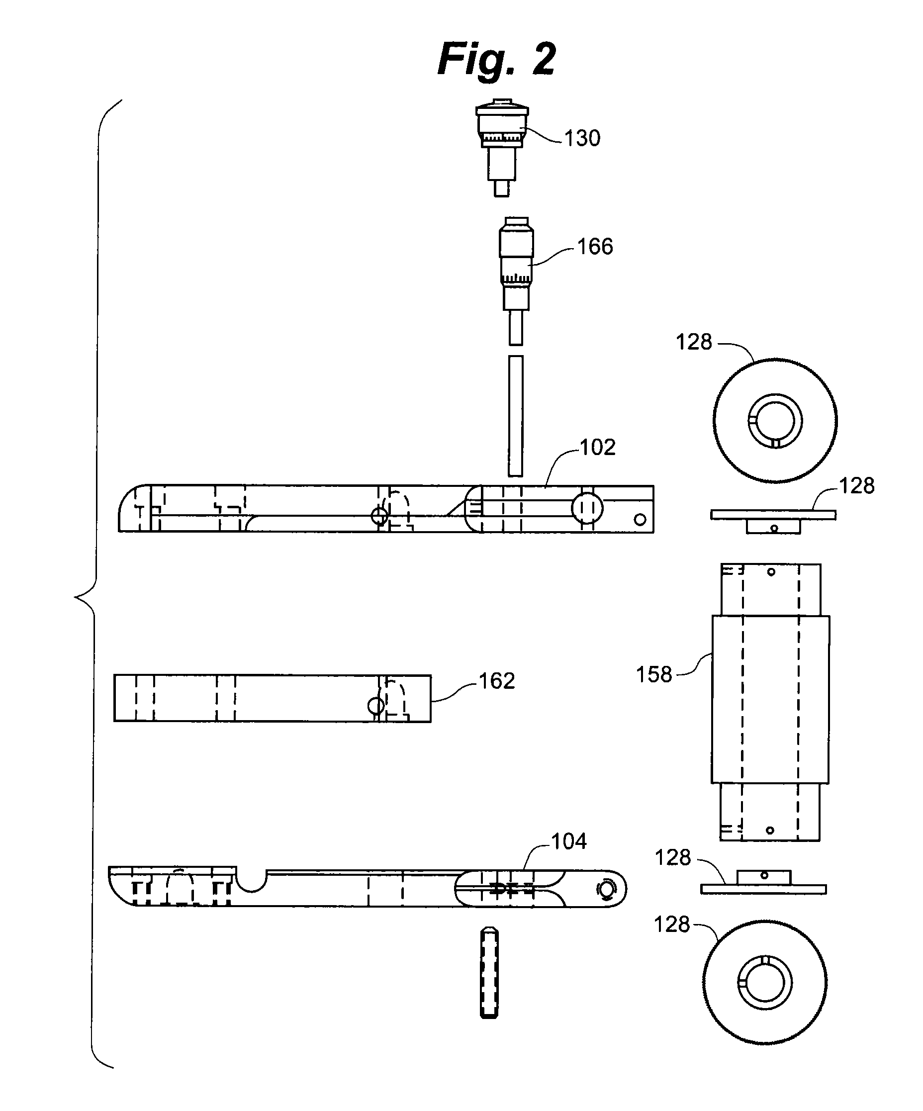
  • Flexographic proofing tools and methods
  • Flexographic proofing tools and methods
  • Flexographic proofing tools and methods

Examples


example

[0120]FIG. 18 illustrates the results of an experiment that tested several kinds of proofers, including those with both trailing and leading edge doctor blades, and measured the density of ink left on a substrate measured at twenty locations. The line depicted with a diamonds, labeled “Vignette Without IR,” is a proofer with a leading edge doctor blade and no metering or ink roll. The line depicted with a squares, labeled “Vignette With IR,” is the proofer identified herein as proofer 200; a proofer with a leading edge doctor blade and an ink roll as described herein. The line depicted with a triangle, labeled “DR-100,” is a conventional proofing tool implementing a trailing edge doctor blade. Even a casual glance at the chart evidences the fact that the leading edge doctor blade with ink roll, the embodiment described in proofer 200, has fewer and less extreme peaks and valleys than either of the other proofers, thus demonstrating its improved consistency.

[0121]FIG. 19 is a table o...


PUM


Abstract

A hand holdable ink proofing tool including an anilox roll and an ink transfer roll, supporting a resilient printing plate. A metering roll adjacent the anilox roll is shiftable to be in contact with the anilox roll and to force ink into cells of the anilox roll; and a leading edge doctor blade is positioned to shear excess ink from a surface of the anilox roll.

Description

RELATED APPLICATION[0001]This application is a continuation of application Ser. No. 12 / 510,789 filed Jul. 28, 2009, which in turn is a Continuation in Part of U.S. patent application Ser. No. 12 / 104,110 filed Apr. 16, 2008, which claims the benefit of U.S. Provisional Patent Application 60 / 925,974 filed Apr. 24, 2007 and U.S. Provisional Patent Application 60 / 964,870 filed Aug. 15, 2007, and also claims the benefit of U.S. Provisional Patent Application 61 / 084,131 filed Jul. 28, 2008 each of which is hereby fully incorporated herein by reference.FIELD OF THE INVENTION[0002]The present invention relates generally to the field of flexographic printing and, more particularly, to portable flexographic ink proofing apparatus for providing proofs of ink samples.BACKGROUND OF THE INVENTION[0003]In the field of flexographic printing ink samples may be obtained by drawing ink over a substrate using a hand ink proofer or by more sophisticated proofing methods. In hand proofing ink is applied ...

Claims


Application Information

Patent Timeline
Patent Type & Authority Applications(United States)
IPC IPC(8): B41K1/22B41N1/00
CPCB41P2200/12B41F5/20B41F31/00
Inventor WESTBY, RONALD K.
Owner PROBITY ENG
Learn More