

Impactor anvil
a technology of impactors and anvils, which is applied in the field of impactors, can solve the problems of prolonging the effective use time of anvils, and achieve the effect of less operator effort or strain, and removal of difficult and time-consuming exercises
- Summary
- Abstract
- Description
- Claims
- Application Information
AI Technical Summary
Benefits of technology
Problems solved by technology
Method used
Image

Examples
Embodiment Construction
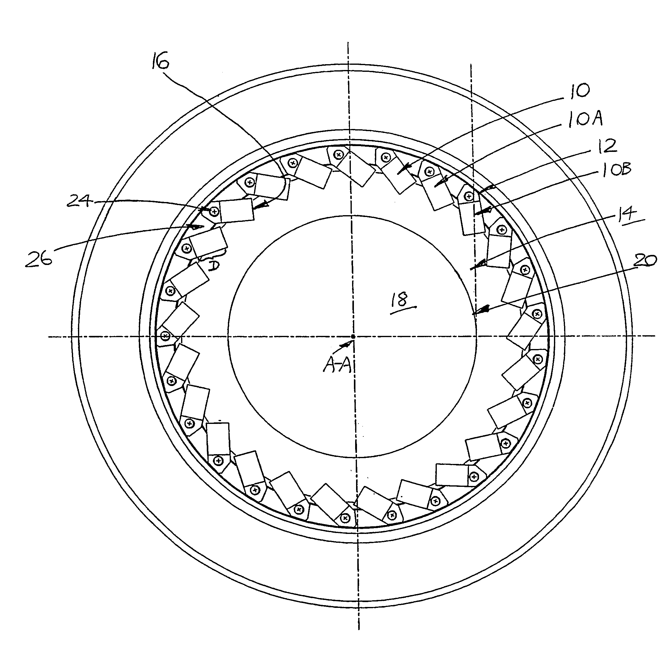
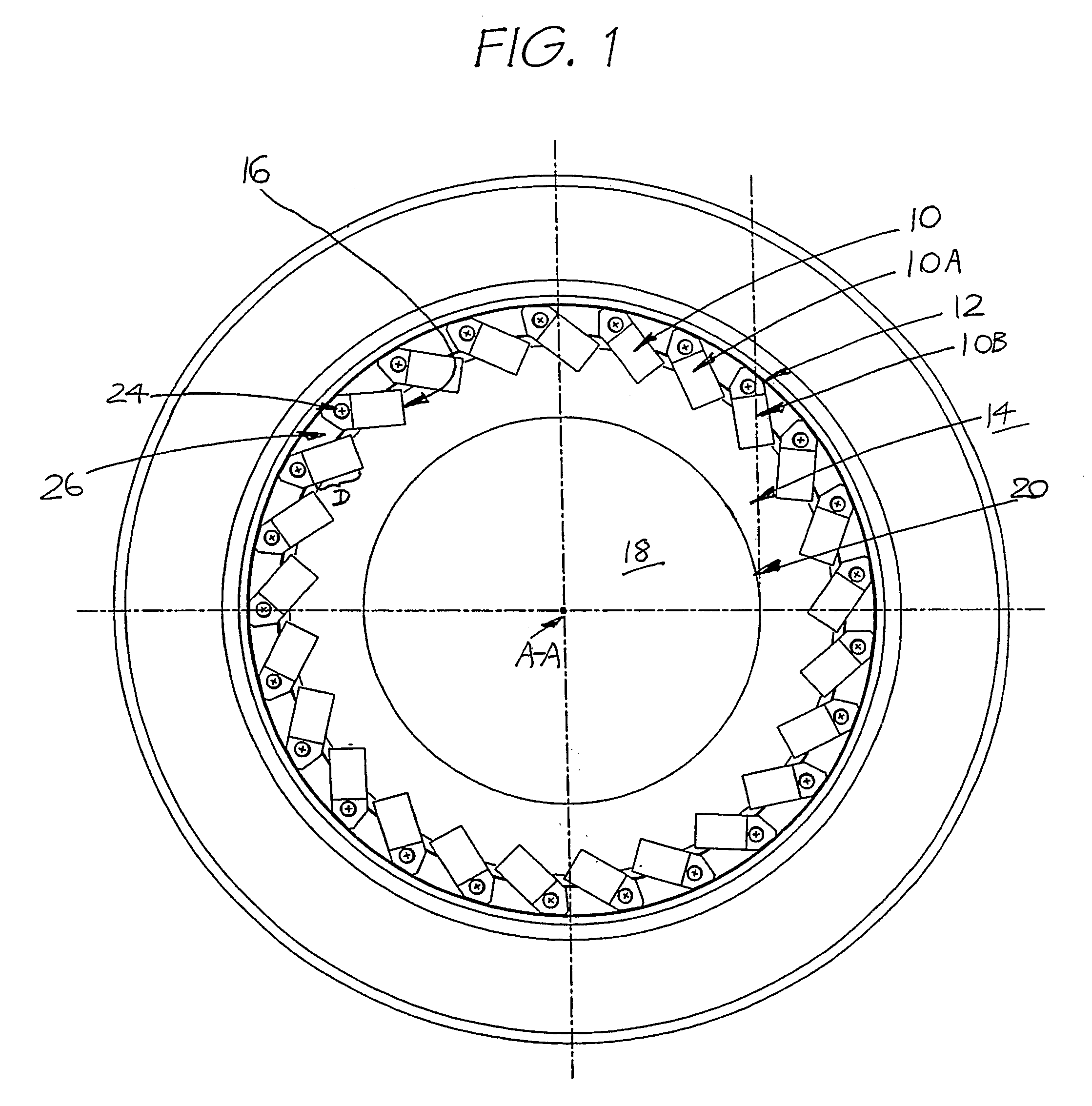
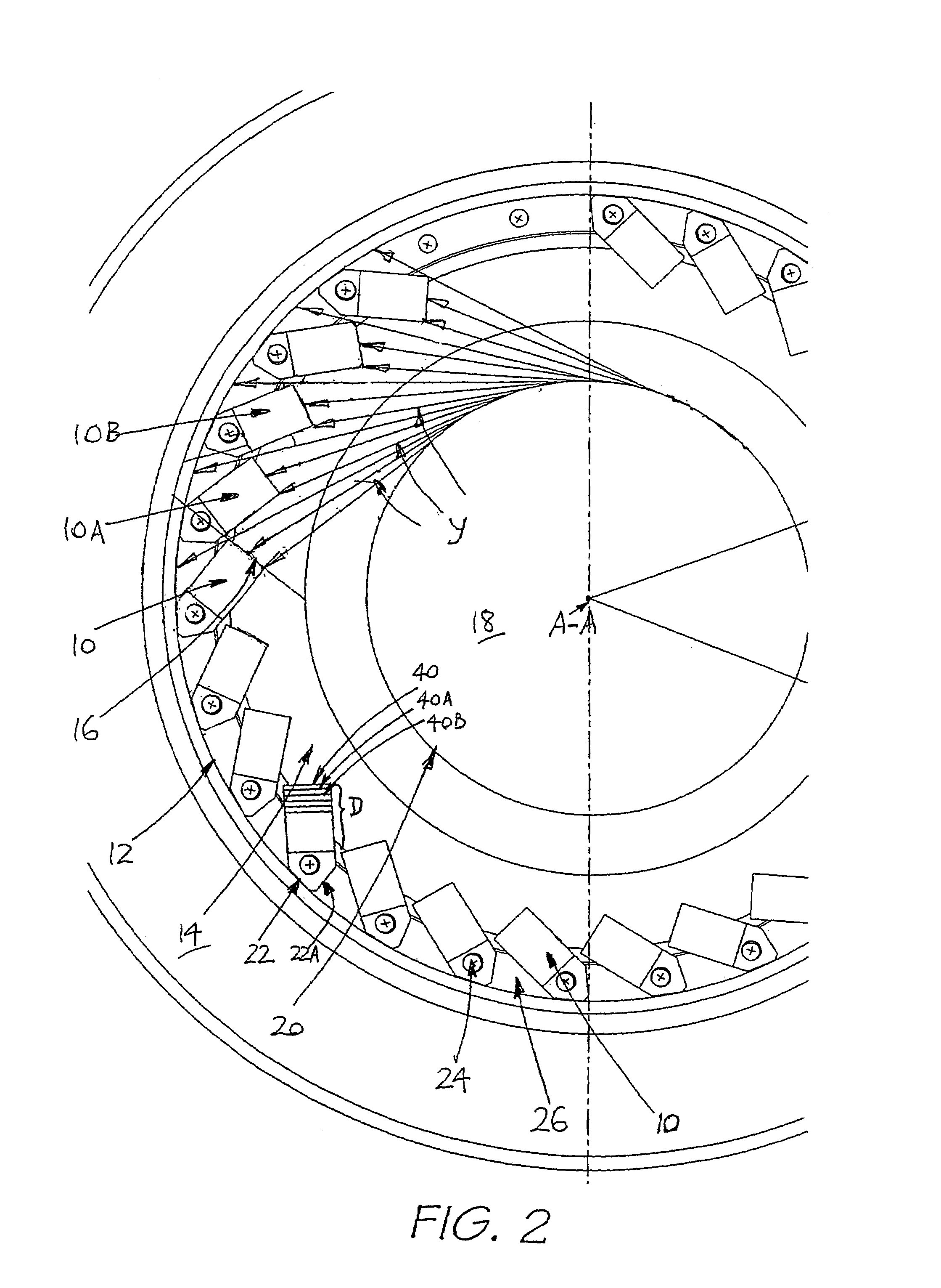
[0037]Referring to the drawings, in FIGS. 1 and 2 a plurality of anvil elements each in the form of a prism-shaped anvil block 10 of rectangular cross-section are arranged evenly about the inner circumferential wall 12 of a rotating shaft impactor chamber 14. Each anvil block has a planar breakage face 16 oriented to receive material thereonto for breakage. The material is directed onto the breakage face 16 by a rotatable impelling device in the form of a rotor 18 located in the centre of the impactor chamber 14. The rotor 18 is arranged to rotate about a vertical axis A-A (shown drawn into the page).
[0038]In the preferred embodiment shown, feed materials for breakage are gravity-fed into the rotor 18. Any relatively coarse feed material which is desired to be reduced to relatively finer size product material can be fed to the rotor 18 including rock, gravel, mineral ores, metalliferous slags, glass and the like, or organic materials such as coal, grain, woodchips etc. The relativel...
PUM
 Abstract
Description
Claims
Application Information