

Methods and apparatus for controlling a continuous flow rotary blood pump
- Summary
- Abstract
- Description
- Claims
- Application Information
AI Technical Summary
Benefits of technology
Problems solved by technology
Method used
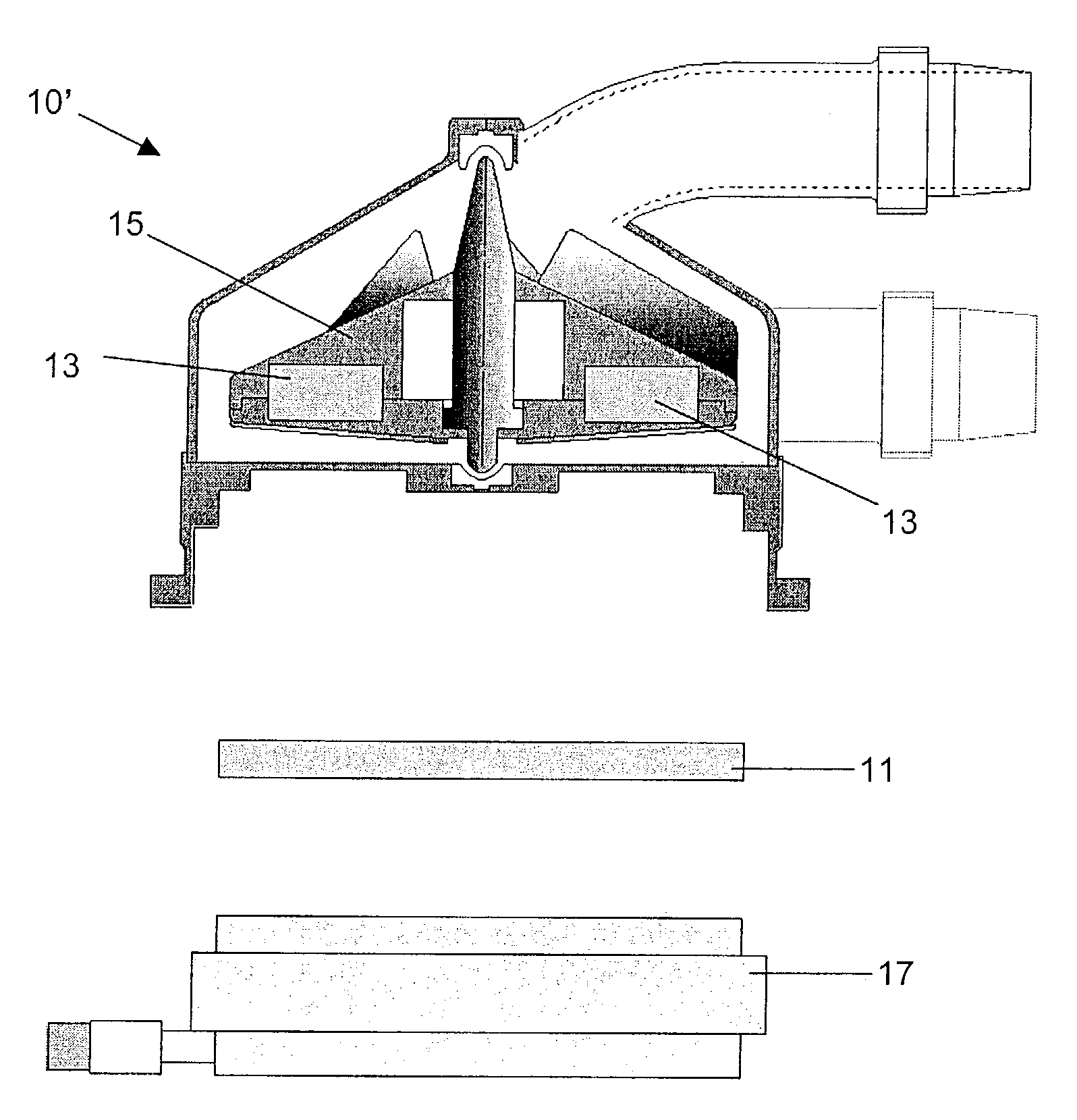
Image

Examples
experiment 1
Evaluation of the Controller for Operating Point Control.
[0062]In this experiment, the behavior of the convergence of the rotational speed of the pump is evaluated when the target rotational speed is purposely changed up and down. The results of this experiment are shown in FIG. 8.
[0063]FIG. 8 shows a graph of the rotational speed versus time, which illustrates an example convergence response time of the pump 10 to the proportional and derivative control applied by the normal operating condition algorithm. In the example shown in FIG. 8, the variation of the pump rotational speed is set at 150 rpm per 5 seconds. The target rotational speed of the pump (shown in dashed lines) is shown as being adjusted upwards at the 4 second mark by 150 rpm (i.e. from 1750 rpm to 1900 rpm). In response to the proportional and derivative control, the actual rotational speed of the pump (shown as a solid line) requires approximately 5 seconds to respond and converge on the new target rotational speed ...
experiment 2
Evaluation of the Controller for Recovering from Abnormal Condition.
[0064]In this experiment, the normal operating condition is changed to an abnormal state by increasing the afterload in the mock circulation loop in order to evaluate the behavior of the controller 20 in recovering from an abnormal condition. The afterload is increased by increasing the total peripheral resistance provided by the clamping device 34.
[0065]FIGS. 9(i) through 9(iv) illustrate the results of this experiment. As shown in FIG. 9(i), by increasing the total peripheral resistance (afterload), the pump flow was decreased. When the pump flow falls under the acceptable range (e.g., 4 L / min as shown in FIG. 9(i)), an abnormal condition is detected and the second abnormal operating condition algorithm is selected by the controller 20. The pressurehead is kept within an acceptable range as shown in FIG. 9(ii). FIG. 9(iii) shows the operation of the second abnormal control algorithm in increasing the target rotati...
experiment 3
Evaluation of Controller for Releasing Pump From a Suction Condition.
[0066]To evaluate the controller 20 in recovering from a suction condition, the position of the inlet port of the pump 10 is changed and the afterload is increased. The position of the inlet port was set near the wall of the bag 28.
[0067]FIGS. 10(i) through 10(iv) illustrate the results of this experiment. As shown in FIG. 10(i), by changing the location of the inlet port and increasing the afterload, a suction condition is generated. Once the current operating condition falls under the normal operating range, the second abnormal operating condition is chosen as discussed above in connection with FIG. 1 and the target rotational speed of the pump is increased. As shown in FIG. 10(ii), the pressurehead can be maintained within the acceptable range even during the occurrence of the suction condition. FIG. 10(iii) shows the increase in the target rotational speed of the pump to recover a normal pump flow range.
[0068]H...
PUM
 Abstract
Description
Claims
Application Information