
Fan type chemical dispersion equipment

a chemical dispersion equipment and fan-type technology, applied in lighting and heating equipment, heating types, separation processes, etc., can solve the problems of unsatisfactory if an increase in efficacy, deficiency of known apparatus services, and limited cartridge size, so as to achieve a larger gripping force and facilitate assembly.

Active Publication Date: 2007-10-23
FUMAKILLA LTD
View PDF22 Cites 30 Cited by
  • Summary
  • Abstract
  • Description
  • Claims
  • Application Information

AI Technical Summary

Benefits of technology

[0021]This feature of the invention permits an apparatus main body, a power supply housing and a chemical receptacle which are independent of each other in volume (size) to be adopted. Variations different in volume of the apparatus main body, the power supply housing and the chemical receptacles may be prepared and selectively used or combined to enable variations different in size of the fan and motor (blower) to be adopted and various settings such as changes in the amount of a chemical and adjustments of the time period for services of the apparatus to be easily accomplished depending on particular places in which the apparatus is used. The above feature also permits the chemical receptacle alone to be exchanged when the chemical therein has been depleted.
[0075]If the object to be caught is a solid such as a belt, then the object can be caught without any trouble by inserting the same into the clip member beyond its pressure foot portion full to its root portion. The object is led to enter up to the space defined with the raised portion or portions, thereby holding the apparatus fastened thereto without coming off.

Problems solved by technology

In the conventional apparatus mentioned above, however, in which a cartridge is designed to be accommodated in the cylindrical housing of a given and limited size, the cartridge must be limited in size by the size of the cylindrical housing, and so must naturally be limited the battery in the number of battery cells and the chemical retainer (chemical accommodating receptacle) in size, too.
The known apparatus has therefore been deficient for services of an extended time period and unsatisfactory if an increase in efficacy is sought.
This battery arrangement thus creating a resistance to the blowing airflow has had the inconvenience that it makes the chemical volatilized, and diffused inefficiently.
Such a conventional chemical receptacle has the problem that when the receptacle main body is loaded from its open top with a chemical impregnated body such as a mass of beads impregnated with a chemical so they rise slightly above its brim and then the cap body is fitted over the main body, a faction of the chemical impregnated particles tends to be pinched between the outer end surface of the cylindrical wall of the main body and the inner surface of the end wall of the cap body, which prevents the cap body from tightly fitting with the receptacle main body.
Also, since the pinched chemical impregnated particles are not exposed to the airflow passing through the chemical receptacle, the chemical impregnated into these particles is hindered from volatilization and thus becomes useless.
Also, having axially opposite portions not identical in form, the conventional chemical receptacle when slide-fitted to the chemical receptacle retaining portion of the power supply housing can be fitted only from one side and cannot be fitted from the other side; hence hard to assemble.
By the way, with a conventional clip type fastening device as described above, the inconvenience has so far been met that the apparatus fastened tends to slip off the object to fall down while the user is at work.
Then, if the object caught between them is so thin as the hem of a pocket, the force to grip it would be too weak to firmly fasten the apparatus of some weight to such an object from which it is suspended.
On the other hand, a thick wear or a waist belt as the object gripped which gives greater deformation to the clip provides greater force to grip therefor without the above inconvenience but, if the object is of a slippy material, the flatness of the surface of the outer wall as its counterpart inconveniently tends to cause the object to slip off the clip and the apparatus here again tends to slip off the object to fall.
While it is possible to increase the force to grip by the pressure foot portion by incorporating the clip into the support mount on the apparatus main body so that the pressure foot portion is held in elastic contact with the outerwall surface under a given pressure, this measure inconveniently not only complicates assembling the clip with the apparatus main body but also poses a problem of strength on the clip by the fact that a large force constantly is left to act on its root portion.

Method used


Image

  • Fan type chemical dispersion equipment
  • Fan type chemical dispersion equipment
  • Fan type chemical dispersion equipment

Examples


Embodiment Construction

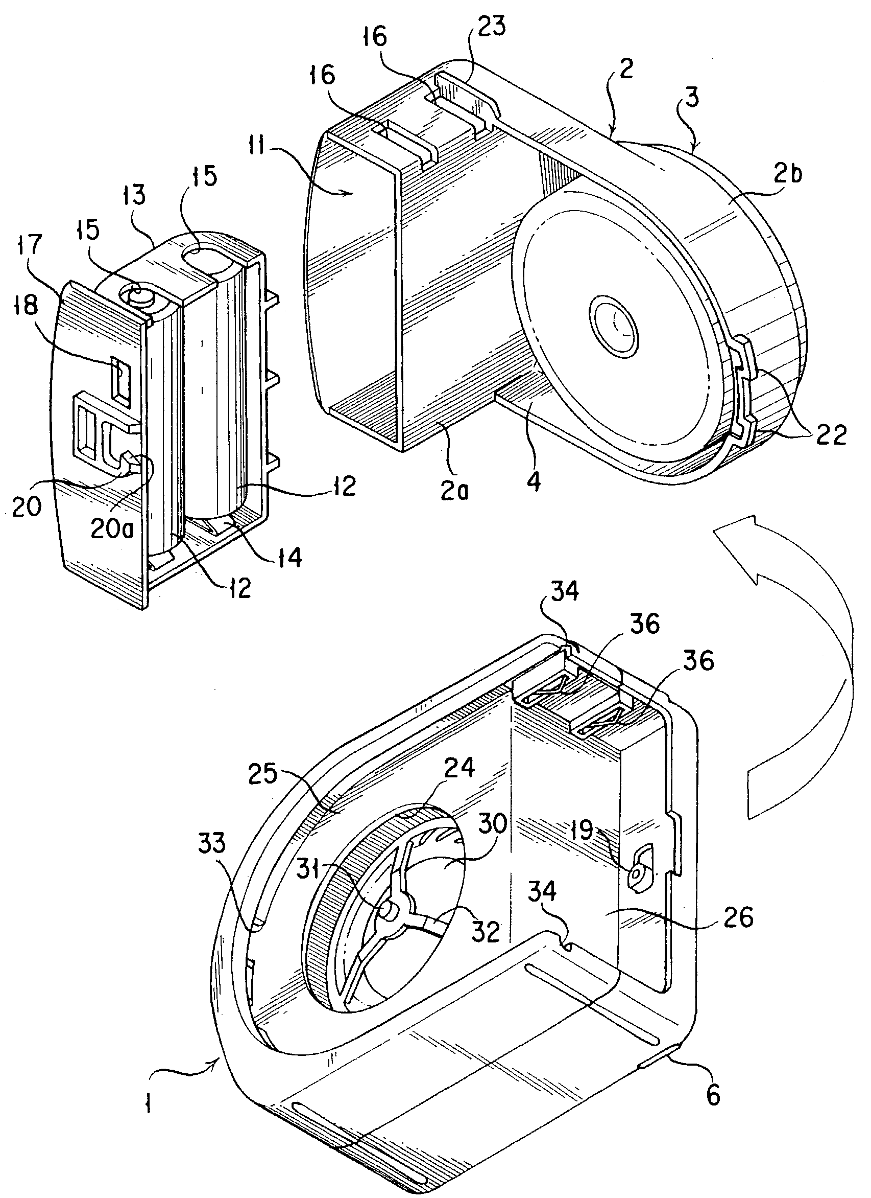
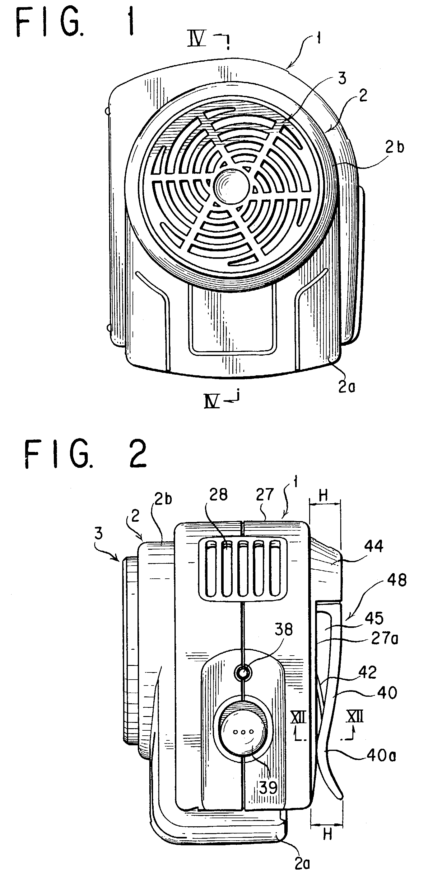
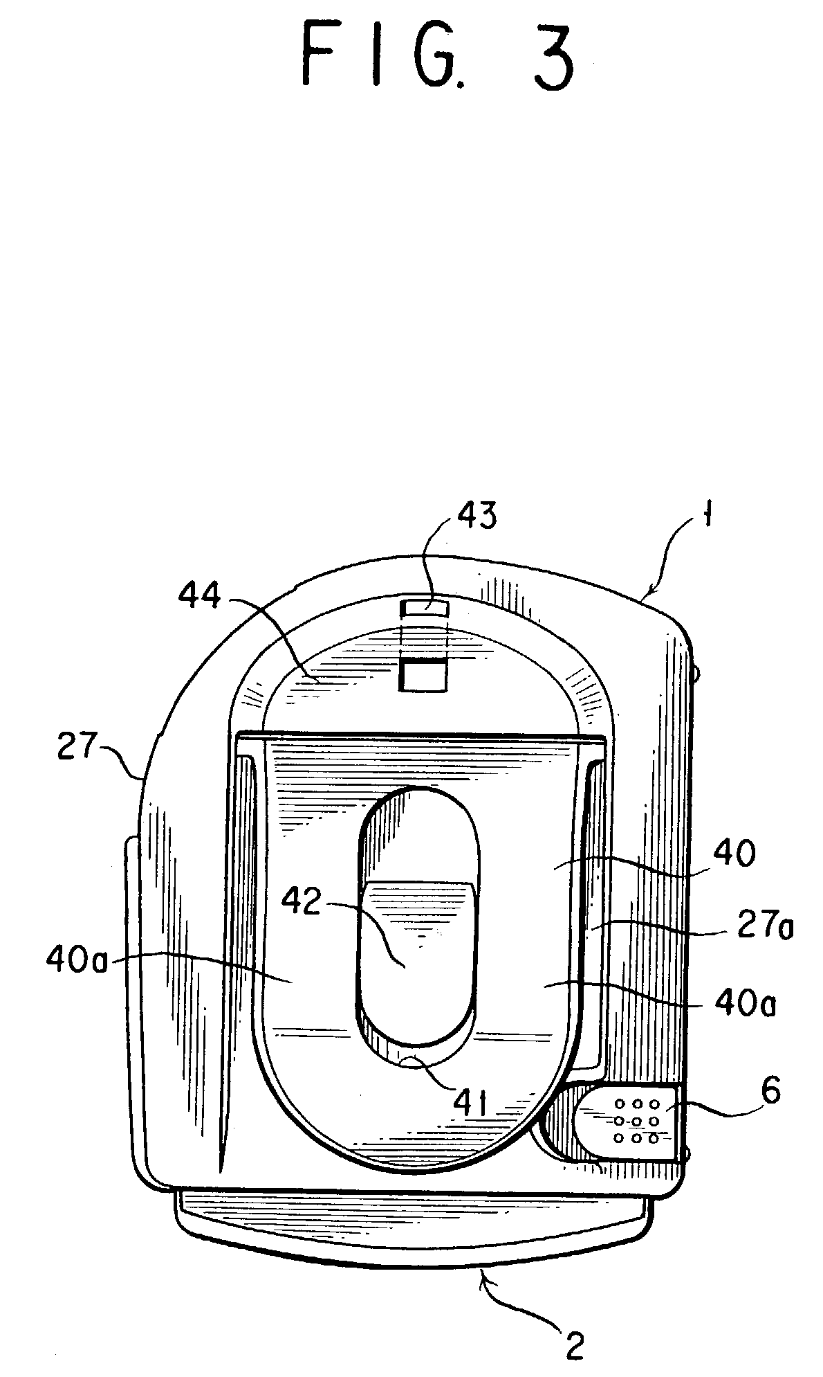
[0112]An explanation is first given in respect of a fan type chemical diffusing apparatus according to the first form of embodiment of the present invention with reference to FIGS. 1 to 16. The apparatus is shown to comprise an apparatus main body 1, a cartridge 2 formed of a power supply housing 2a and a chemical receptacle retainer 2b which are united together, and a chemical receptacle 3. The chemical receptacle 3 here is adapted to be fitted into, held by and disengaged from a chemical receptacle retaining section 4 of the chemical receptacle retainer 2b. And, the cartridge 2 is adapted detachably to slide-fit with the apparatus main body 1. Namely, slidably inserted into the apparatus main body 1 in a direction perpendicular to the central axis of the chemical receptacle retaining section 4, the cartridge 2 is adapted to come into engagement with the apparatus main body 1. To detach the cartridge 2 or disengage it from the apparatus main body 1, an engagement releasing button 6...


PUM

PropertyMeasurementUnit
Pressureaaaaaaaaaa
Flow rateaaaaaaaaaa
Volumeaaaaaaaaaa

Abstract

A fan type chemical dispersion equipment, wherein a chemical container (3) and a power supply storage body (2a) are disposed detachably from an equipment body (1) and so as not to be volumetrically limited with each other, whereby, because the equipment body, chemical container, and power supply storage body can be volumetrically formed independently of each other, the settings of a chemical holding amount relative to a fan air blow amount and long or short service time can be performed easily, the chemical container being capable of preventing a chemical impregnated body from being caught between the end face of a chemical container body (3a) and a cover body (3b), and a clip device being capable of firmly fixing the fan type chemical dispersion equipment to the held materials ranging from thin to thick ones.

Description

[0001]This application is a U.S. National Phase of International Application No. PCT / JP01 / 08261 filed on Sep. 21, 2001.BACKGROUND OF THE INVENTION[0002]1. Technical Field[0003]The present invention relates to a fan type chemical diffusing apparatus for volatilizing and diffusing a chemical in an airflow produced by a motor driven fan or blower, and a receptacle for the chemical for use with such a fan type chemical diffusing apparatus, as well as a clip type fastening device for fastening a fan type chemical diffusing apparatus to an object such as apparel of its user.[0004]2. Description of the Prior Art and Objects of the Invention[0005]A fan type chemical diffusing apparatus designed to volatilize and diffuse a chemical in an airflow produced by a motor driven fan has been known as described in JP S53-14329 A.[0006]The apparatus described in that patent literature comprises a cylindrical housing that constitutes an apparatus main body equipped with a motor and fan, in which a car...

Claims


Application Information

Patent Timeline
IPC IPC(8): A62B7/08A01M1/20A01M29/12A01N25/18A61L9/12
CPCA01M1/2033A01M1/2055A01M1/2072A61L9/122A01M29/12A01N25/18A61L9/12A01M1/2077A01M1/20
Inventor YAMAMOTO, KAZUNORIYAMASAKI, SATOSHI
Owner FUMAKILLA LTD
Learn More