Armature core of rotating electric machine
a technology of rotating electric machines and armatures, which is applied in the direction of rotating parts of magnetic circuits, magnetic circuits characterised by magnetic materials, and magnetic circuits. it can solve the problems of complex work for fixing individual divided cores to the boss one by one, and the difficulty of forming a space for accommodating joint parts, etc., to achieve the effect of improving assembly work efficiency
- Summary
- Abstract
- Description
- Claims
- Application Information
AI Technical Summary
Benefits of technology
Problems solved by technology
Method used
Image
Examples
first embodiment
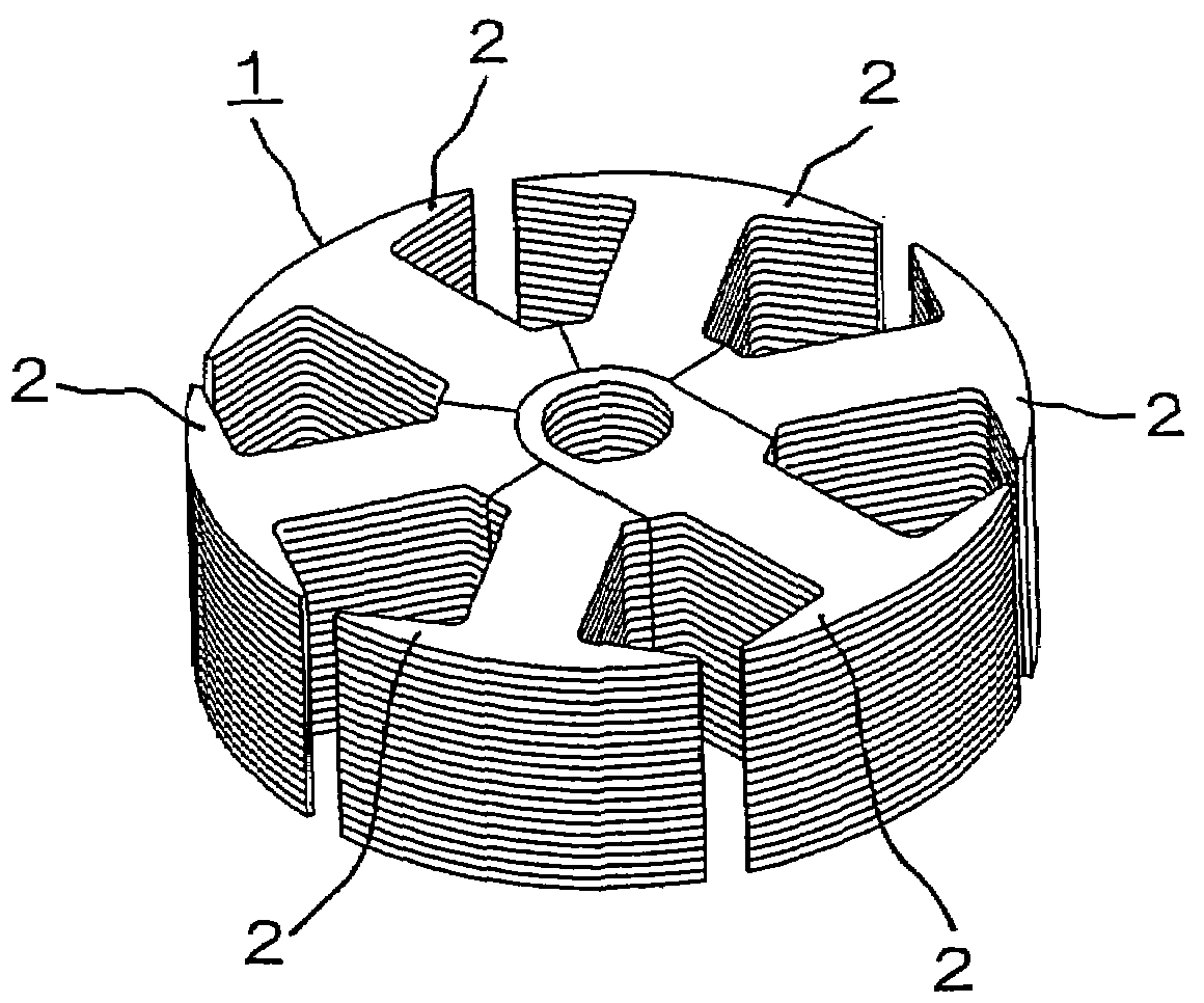
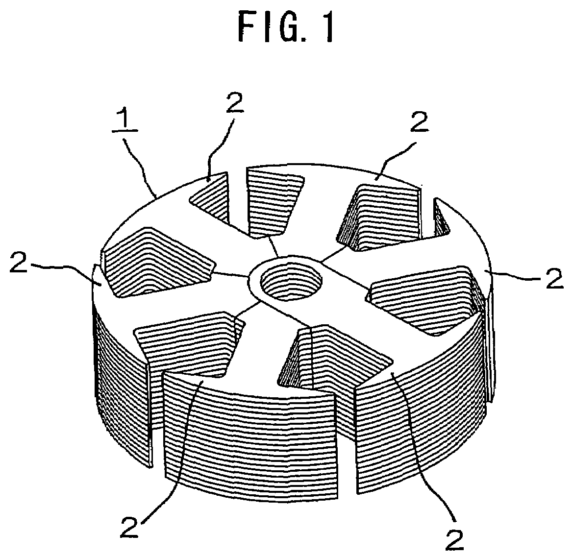
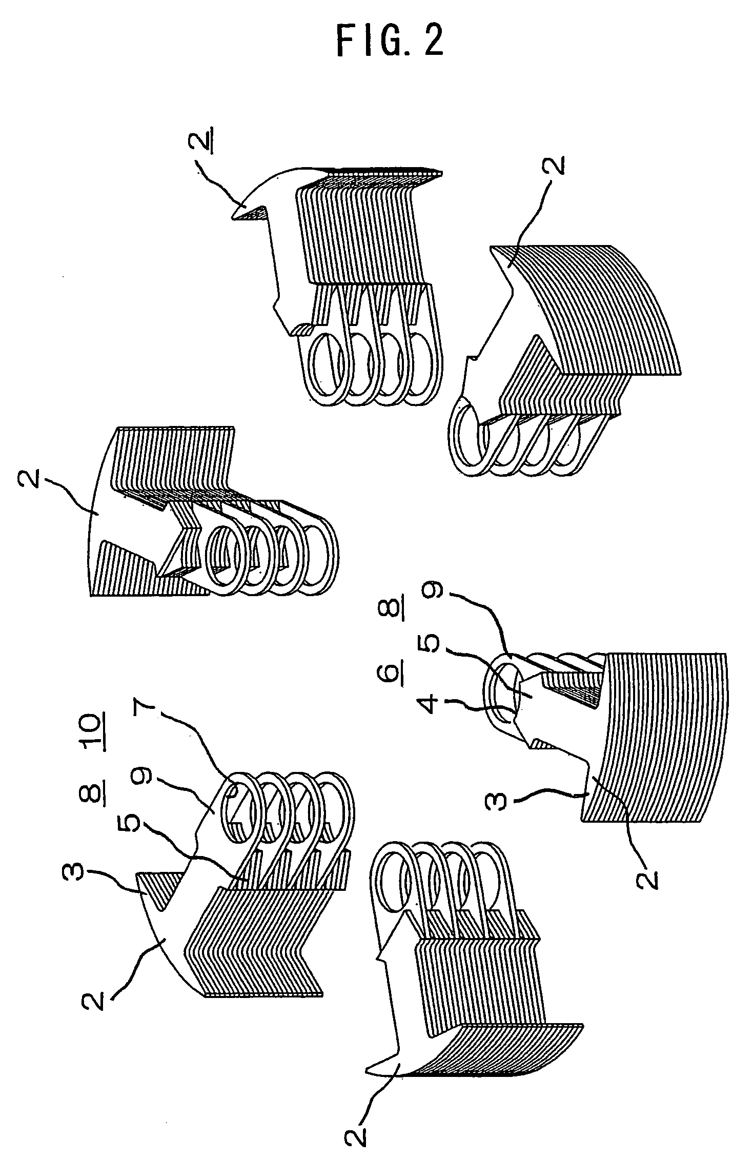
[0026]FIG. 1 is a perspective view showing the structure of an armature core of a rotating electric machine according to a first embodiment of this invention, FIG. 2 is an exploded perspective view showing the rotating electric machine armature core of FIG. 1, FIG. 3 is a perspective view showing a state in which one of magnetic tooth sections of the rotating electric machine armature core of FIG. 1 has been detached, FIG. 4 is a plan view showing the rotating electric machine armature core of FIG. 1, FIG. 5 is a cross-sectional view showing a cross section taken along a line V-V of FIG. 4, FIG. 6 is a diagram showing a process of winding coils on the rotating electric machine armature core of FIG. 1, FIG. 7 is a perspective view showing an example in which the magnetic tooth sections of the rotating electric machine armature core of FIG. 1 have been fixedly combined into a single body by forcibly inserting a rotary shaft, and FIG. 8 is a cross-sectional view showing an example in w...
second embodiment
[0034]A rotating electric machine armature core 21 according to a second embodiment of this invention is configured by combining a first magnetic tooth section 22 disposed at a central position and a plurality of second magnetic tooth sections 31 disposed in surrounding areas of the first magnetic tooth section 22 as shown in FIG. 9. FIG. 10 is a fragmentary cross-sectional view showing the structure of a principal part of the rotating electric machine armature core of FIG. 9.
[0035]The first magnetic tooth section 22 is configured by laminating specific numbers of first sheet members 26 and second sheet members 30 as shown in FIG. 11. Each of the first sheet members 26 includes a ring like portion 24 having a through hole 23 at a central part and a plurality of magnetic tooth portions 25 formed to extend from around this ring like portion 24 at specific intervals along a circumferential direction. Each of the second sheet members 30 has the second sheet member 30 which includes a se...
third embodiment
[0040]FIG. 13 is a fragmentary cross-sectional view showing the structure of a principal part of a rotating electric machine armature core according to a third embodiment of this invention, in which elements similar to those of the aforementioned first embodiment are designated by the same reference numerals and a description of such elements is omitted.
[0041]The rotating electric machine armature core of the third embodiment of this invention is configured in such a manner that surfaces of individual magnetic tooth sections 2 are covered with molding resin 42 and extreme end parts 43 of a magnetic tooth portion 3 of each magnetic tooth section 2 extend so that a slot opening between extreme ends of one magnetic tooth portion 3 and another is closed. The aforementioned structure makes it possible to decrease windage loss by reducing passage flow resistance of air gaps and thereby increase the efficiency of a rotating electric machine.
PUM
 Abstract
Description
Claims
Application Information
 - R&D
- Intellectual Property
- Life Sciences
- Materials
- Tech Scout
- Unparalleled Data Quality
- Higher Quality Content
- 60% Fewer Hallucinations
Browse by: Latest US Patents, China's latest patents, Technical Efficacy Thesaurus, Application Domain, Technology Topic, Popular Technical Reports.
© 2025 PatSnap. All rights reserved.Legal|Privacy policy|Modern Slavery Act Transparency Statement|Sitemap|About US| Contact US: help@patsnap.com


