Cooling system for electronic devices

a technology for electronic components and cooling blocks, which is applied in indirect heat exchangers, lighting and heating apparatuses, instruments, etc., can solve the problems of difficult direct installation of cooling blocks on electronic devices such as hard-disk drives, video cards, memory cards,

Inactive Publication Date: 2007-10-23
CHEON KIOAN
View PDF10 Cites 72 Cited by
  • Summary
  • Abstract
  • Description
  • Claims
  • Application Information

AI Technical Summary

Problems solved by technology

It is difficult to make these blocks in such a way that they can be put into contact with uneven surfaces.
Also, the cooling blocks are difficult to directly install on such electronic devices as hard-disk drives, video cards, memory cards, or a PCB.

Method used


Image

  • Cooling system for electronic devices
  • Cooling system for electronic devices
  • Cooling system for electronic devices

Examples


Embodiment Construction

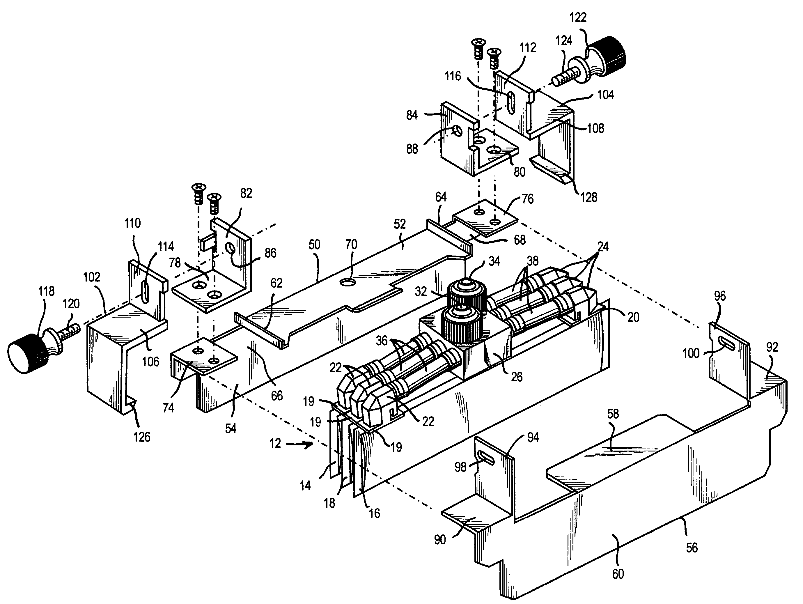
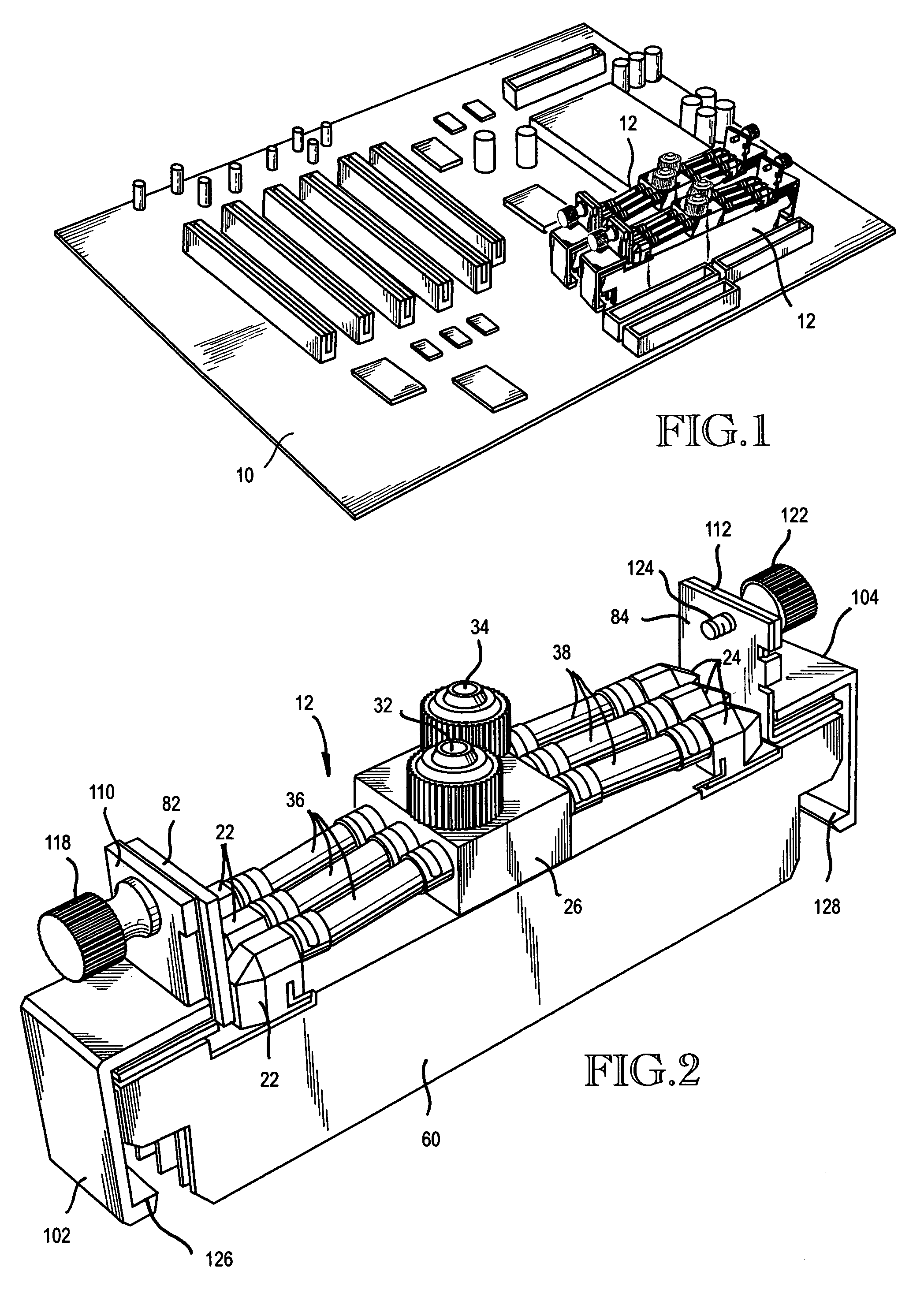
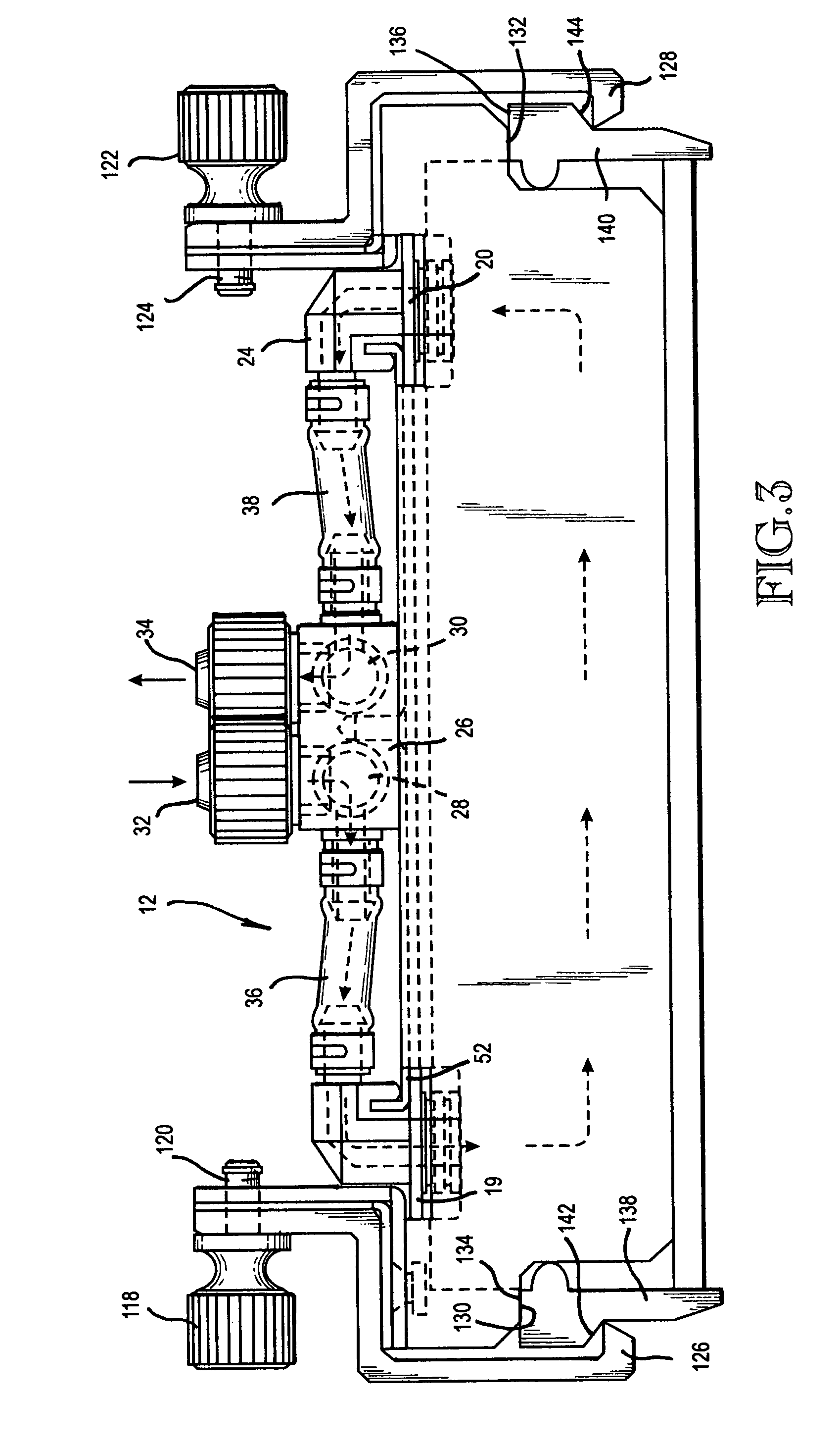
[0020]FIG. 1 shows a mounting board 10 for electronic components that are parts of a computer, for example. FIG. 1 shows two side-by-side cooling assemblies 12. FIGS. 2-4 show one of the cooling assemblies 12. The cooling assembly 12 comprises a plurality of pouch bodies formed of sheet material that is deformable. The illustrated embodiment comprises three poach bodies and they are designated 14, 16, 18. These pouch bodies may be constructed in the manner disclosed in U.S. Ser. No. 10 / 761,503, the contents of which is hereby incorporated herein. Herein, pouch body 14 is sometimes referred to as the first pouch body. Pouch body 16 is sometimes referred to as the second pouch body. Pouch body 18 is sometimes referred to as the third pouch body. The first and second pouch bodies 14, 16 are positioned at the sides of the assembly 12. Pouch body 18 and any additional pouch bodies are positioned between the pouch bodies 14, 16. Pouch bodies 14, 16, 18 are positioned in a side-by-side rel...


PUM


Abstract

A plurality of pouch bodies (14, 16, 18) are supported side-by-side from an assembly that includes a manifold block (26). The manifold block (26) includes an inlet manifold (28) and an outlet manifold (30). A liquid coolant (e.g. water) is delivered into the inlet manifold (28) via an inlet fitting (32). The liquid flows from the inlet manifold (28) into and through inlet passageways (36) which connect the inlet manifold (28) with inlet fittings (22) leading into a common end of the pouch bodies (14, 16, 18). The cooling liquid flows into the pouch bodies (14, 16, 18) and through them to outlet fittings (24) at the opposite ends of the pouch bodies (14, 16, 18). The coolant flows from the outlet fittings (24) through outlet conduits (38) to and into the outlet manifold (30). The coolant flows from outlet manifold 30 out through an outlet port (34). Electronic components to be cooled are placed between the pouch bodies (14, 16, 18).

Description

RELATED APPLICATION [0001]This is a continuation-in-part of U.S. Ser. No. 10 / 761,503, filed Jan. 20, 2004, as a continuation-in-part of application Ser. No. 10 / 241,118, filed Sep. 11, 2002 now abandoned.TECHNICAL FIELD [0002]This invention relates to a cooling system for electronic components utilizing a liquid coolant. More particularly, it relates to such a system comprising a plurality of pouch bodies, each formed of a flexible sheet material making the pouch body deformable, so that the pouch bodies can be moved against and conform in shape to uneven surfaces. Cooling fluid is circulated through the pouch bodies for cooling objects having the uneven surfaces.BACKGROUND OF THE INVENTION [0003]It is well known that computers include components that produce heat. Various types of cooling systems have been proposed for removing heat from the computer components to maintain the computer within acceptable operating temperature limits. The prior art includes cooling systems utilizing a...

Claims


Application Information

Patent Timeline
Patent Type & Authority Patents(United States)
IPC IPC(8): H05K7/20F28D15/00F28F7/00
CPCG06F1/20G11B33/142G06F2200/201
Inventor CHEON, KIOAN
Owner CHEON KIOAN
Why Eureka
Try Eureka