Bit recovery scheme for an asymmetric data channel

Inactive Publication Date: 2007-10-23
THOMSON LICENSING SA
View PDF6 Cites 8 Cited by
  • Summary
  • Abstract
  • Description
  • Claims
  • Application Information

AI Technical Summary

Benefits of technology

[0015]Usually the modulation of a channel data stream is subject to certain runlength restrict

Problems solved by technology

However, the data patterns recorded on a recording medium may be distorted by an asymmetric data writing procedure.
Due to the asymmetry a simple slicing algorithm is not

Method used


Image

  • Bit recovery scheme for an asymmetric data channel
  • Bit recovery scheme for an asymmetric data channel
  • Bit recovery scheme for an asymmetric data channel

Examples


Embodiment Construction

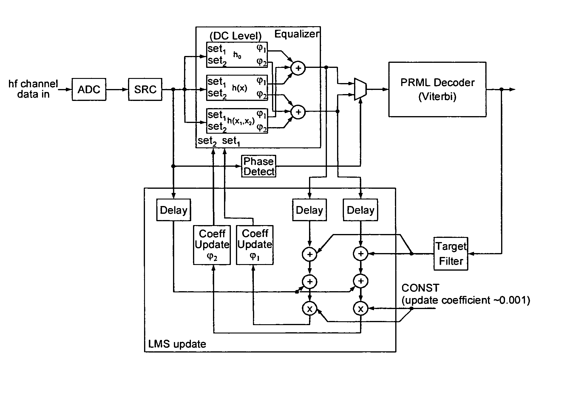
[0026]In FIG. 4 a solution according to the invention using an equalizer with a single filter but two coefficient sets is shown. Instead of an FIR filter a polynomial filter (Volterra Filter), which is simplified to an additional DC level and a multiplier to create a quadratic filter stage, is used. The algorithm representing the non-linear filter can be expressed with the following (simplified) equation 1:

yk=h0+h1(x(k))+h2(x(k),x(k))  (1)

[0027]The known approach using an FIR filter only considers the term h1(x(k)). The polyphase term h2, which is basically a quadrature of the incoming signal, requires an additional DC compensation, which is taken into account by the factor h0.

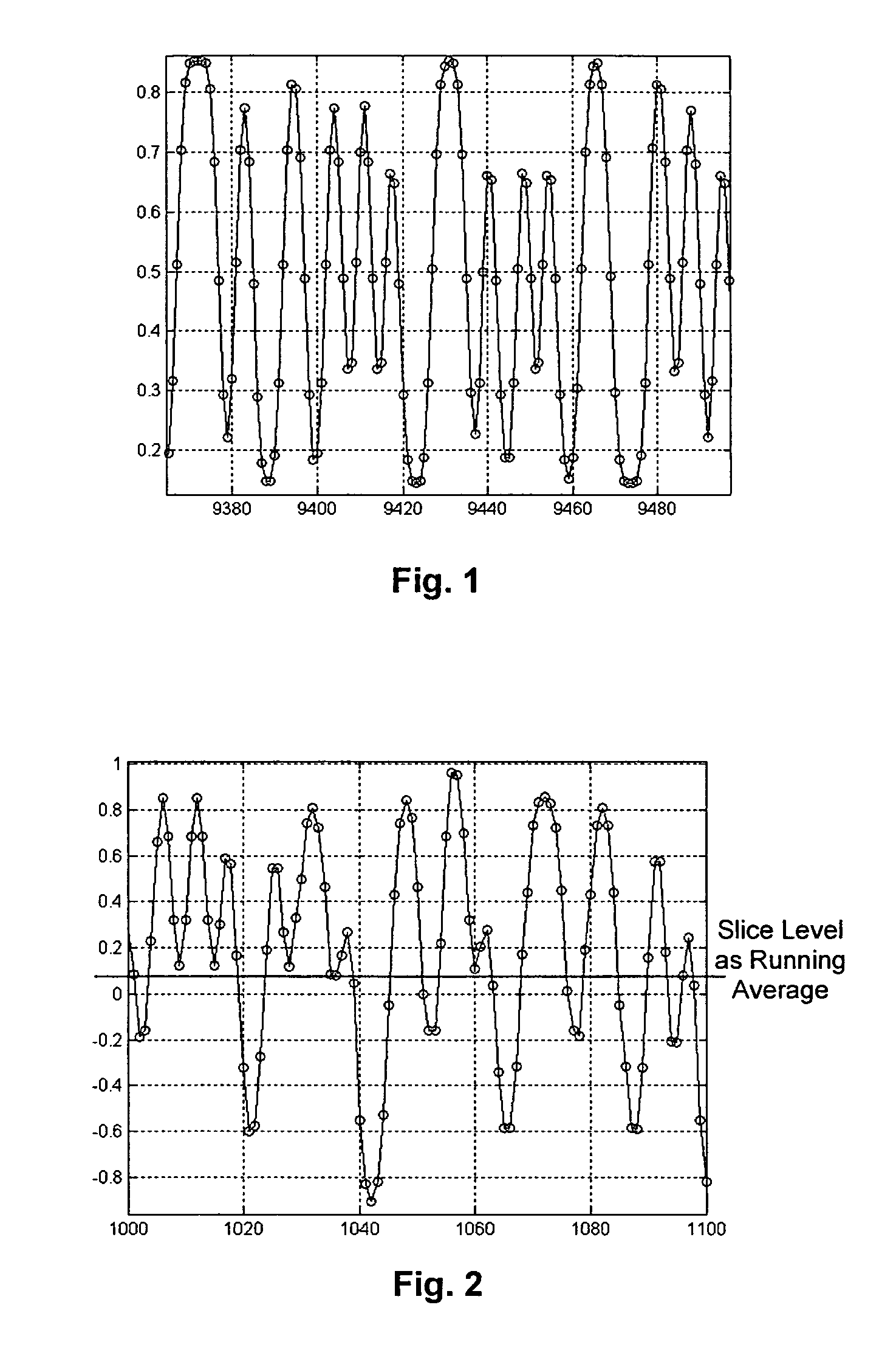
[0028]FIG. 5 to FIG. 8 show simulation results obtained with the solution according to the invention. In FIG. 5 the differences between signals generated by the dual equalizer and Viterbi decoded data. FIG. 6 compares the digital sum value (DSV) of the recovered data with the reference data. In the graph, erro...


PUM


Abstract

A method for bit recovery in an asymmetric data channel, the method comprising the steps of: providing a non-linear equalization filter with two coefficient sets; using the non-linear equalization filter with a first coefficient set for compensating defects of a first type of transition between different storage states; and using the non-linear equalization filter with a second coefficient set for compensating defects of a second type of transition between different storage states.

Description

FIELD OF THE INVENTION[0001]The present invention relates to a method and a device for bit recovery in an asymmetric data channel, and to an apparatus for reading from and / or writing to recording media using such method or device.BACKGROUND OF THE INVENTION[0002]In current harddisk and optical disk applications partial response maximum likelihood detectors (PRML, Viterbi) are used for recovering the data from a channel data stream. FIG. 1 shows high frequency channel data representing a data stream from an exemplary optical channel signal. The channel data are not distorted by asymmetry. In this case a data slicing process is easily able to distinguish between two different signal states (high and low). However, the data patterns recorded on a recording medium may be distorted by an asymmetric data writing procedure. For example, on optical recording media one reason for asymmetry is Blooming, which is caused by non-linear effects during data recording. FIG. 2 shows an example of a ...

Claims


Application Information

Patent Timeline
IPC IPC(8): H03K5/159G11B20/14G11B20/02G11B20/10H03H17/02H03M5/14H03M7/46
CPCG11B20/10009G11B20/10212H03M7/46H03M5/145G11B20/1426G11B20/02
Inventor KOCHALE, AXELGAEDKE, KLAUSTIMMERMANN, FRIEDRICHTHEIS, OLIVER
Owner THOMSON LICENSING SA
Why Eureka
Try Eureka