FSK signal detector

a signal detector and frequency shift technology, applied in the field of fsk (frequency shift keying) signal detectors, can solve the problems of adversely affecting the characteristic of fsk signal detectors and frequency detection, and achieve the effect of simplifying circuit configuration and less susceptibl

Active Publication Date: 2007-10-23
LAPIS SEMICON CO LTD
View PDF5 Cites 2 Cited by
  • Summary
  • Abstract
  • Description
  • Claims
  • Application Information

AI Technical Summary

Benefits of technology

[0007]It is an object of the present invention to overcome the disadvantages of the prior art as mentioned above and to provide an FSK signal detector in a simple circuit configuration which prevents fluctuations in the amplitude of an FSK signal from adversely affecting the characteristic of frequency detection.
[0013]According to the present invention, an input FSK signal is converted to a binarized signal having the amplitude of “0”, “1” by the binarizing means, and the frequency of the binarized signal is detected through digital processing using the 2n-stage shift register and adding means, so that the circuit configuration can be simplified without the need for using parts such as an A / D converter.
[0014]Also, the amplitude fluctuation component of the input FSK signal is suppressed by the amplitude limiting means, and its amplitude is binarized by the binarizing means, so that the detection characteristic can be made less susceptible to fluctuations in amplitude, unlike the conventional detection scheme which obtains the phase from the amplitudes of I, Q signals.
[0015]Further, the FSK signal detector generates a DC offset which varies in accordance with a frequency offset included in the FSK signal, and cancels a frequency offset component included in the frequency detection output by this DC offset, so that the FSK data can be generated from the frequency detection output without being affected by the frequency offset.

Problems solved by technology

However, the foregoing FSK signal detector detects the frequency on the basis of the amplitude information of the I, Q signals, fluctuations in the amplitudes of the I, Q signals due to noise and the like, if any, would adversely affect the characteristic of the frequency detection.
Also, the FSK signal detector is problematic in that it needs such parts as A / D converters, and involves a complicated circuit configuration because the amplitude information of the I, Q signals is represented using a plurality of bits.

Method used


Image

  • FSK signal detector
  • FSK signal detector
  • FSK signal detector

Examples


Embodiment Construction

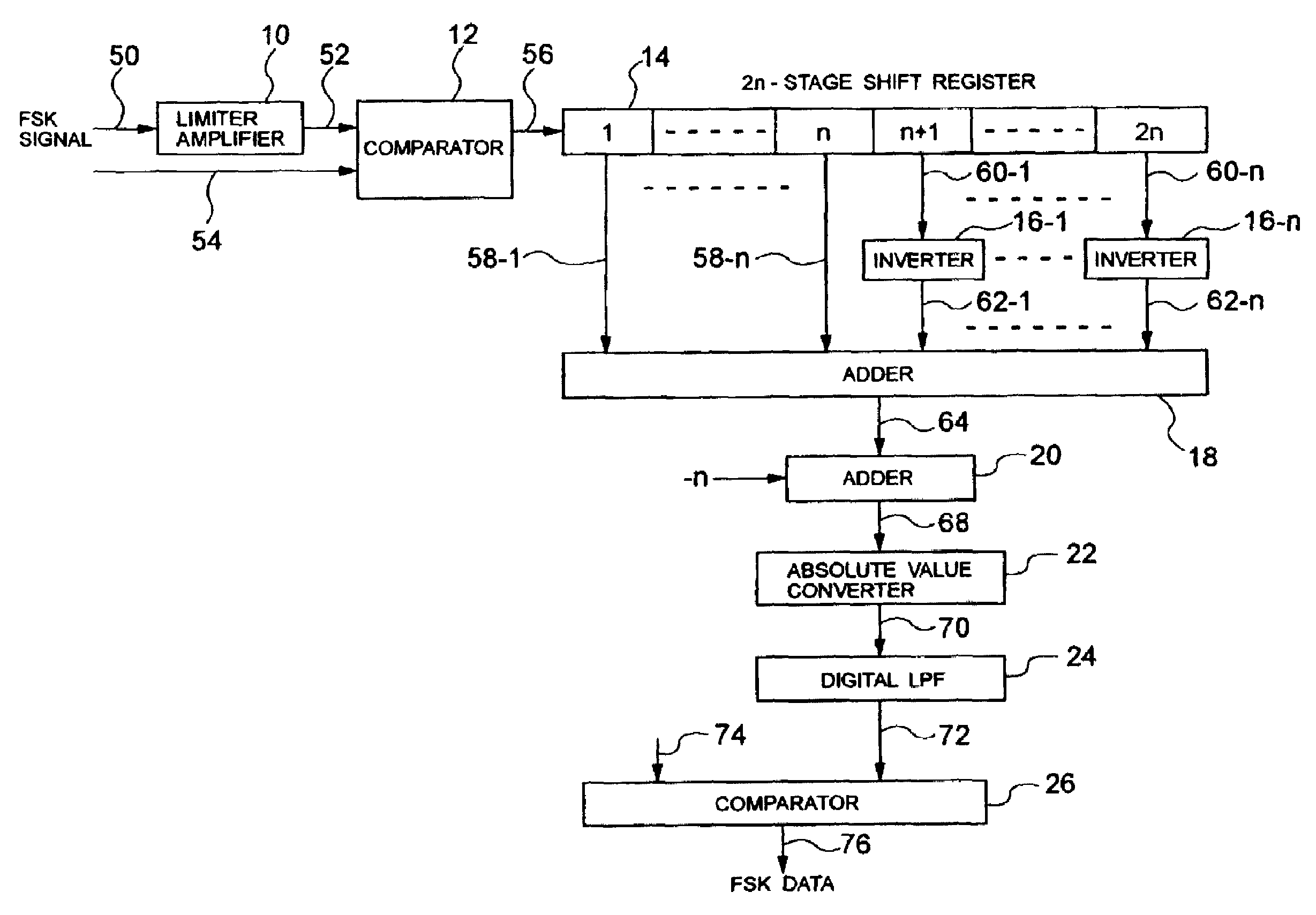
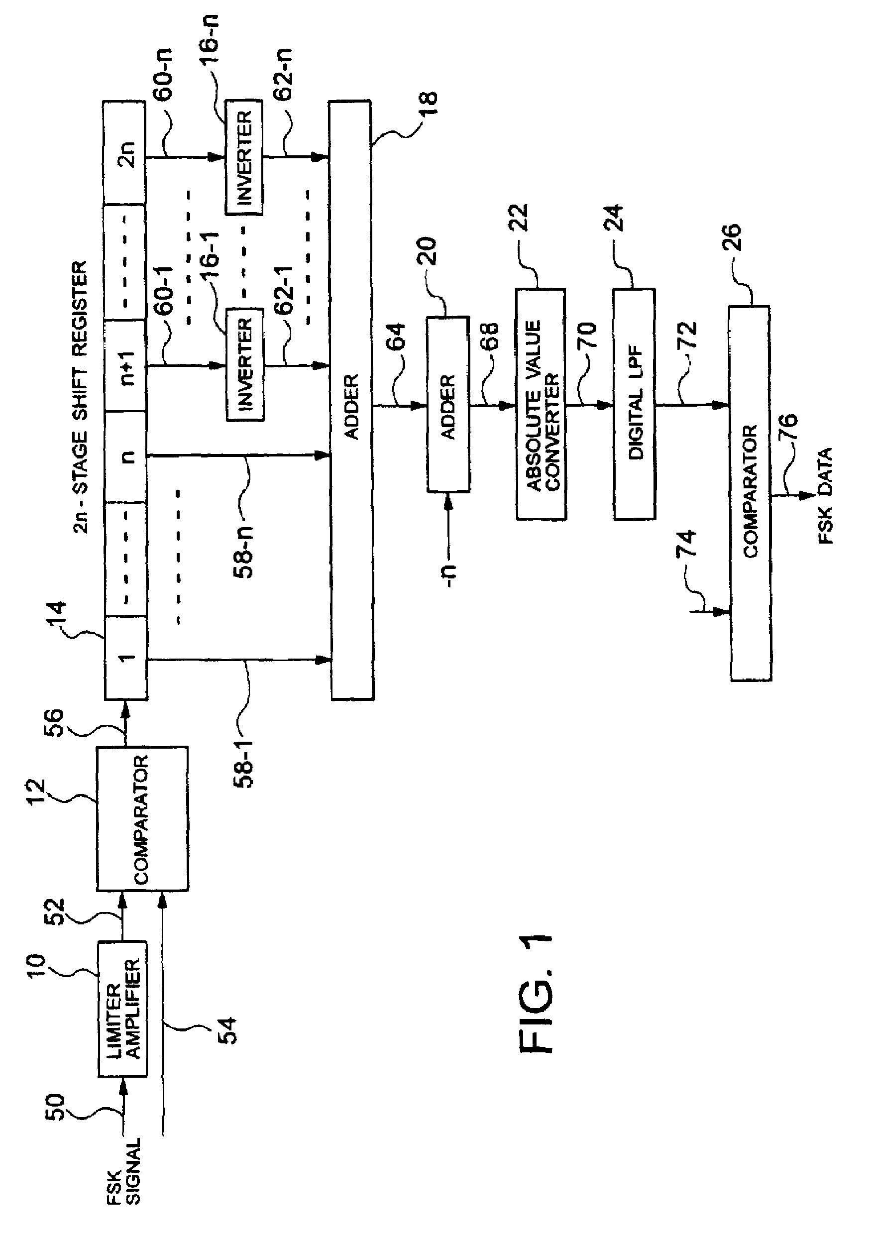
[0035]Embodiments of an FSK signal detector according to the present invention will be described in detail with reference to the accompanying drawings. Referring to FIG. 1, the FSK signal detector of the embodiment detects the frequency of an FSK signal through digital processing to output FSK data 76, and comprises a limiter amplifier 10, comparators 12, 26, a 2n-stage shift register 14, inverters 16-1-16-n, adders 18, 20, an absolute value converter 22, and a digital LPF (low pass filter) 24. In FIG. 1, reference numerals added to connection lines indicate signals which appear on those connection lines.

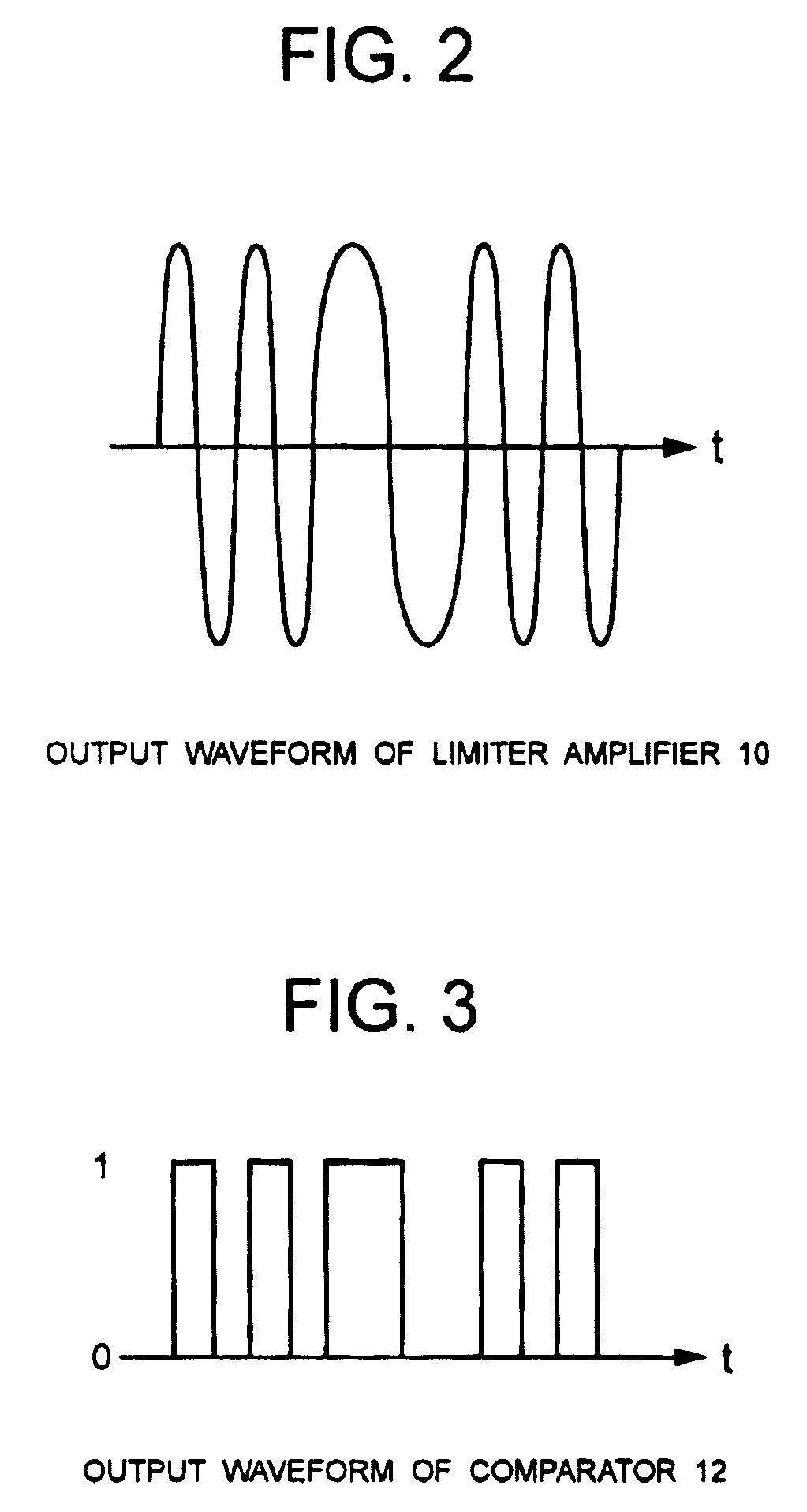
[0036]The limiter amplifier 10 is applied with the FSK signal 50 which has been down-converted from a high-frequency received signal to an IF received signal of several MHz. The limiter amplifier 10 is an amplitude limiting circuit which limits the amplitude of the FSK signal 50 to suppress an amplitude fluctuating component thereof. With this circuit, the frequency detection can be...


PUM


Abstract

A detector includes a binarizer for binarizing the amplitude of an input FSK signal; a 2n-stage shift register having 2n registers for sequentially shifting the FSK signal binarized by the binarizer in response to a clock; and an adder for calculating a sum of a total number of FSK signals having the value of “1” or “0” among FSK signals stored in a first to an n-th register of the 2n-stage shift register and a total number of FSK signals having the value of “0” or “1” among FSK signals stored in an (n+1)th to a 2n-th register.

Description

BACKGROUND OF THE INVENTION[0001]1. Field of the Invention[0002]The present invention relates to an FSK (Frequency Shift Keying) signal detector for detecting an FSK signal, and more particularly, to an FSK signal detector for detecting an FSK signal through digital processing.[0003]2. Description of the Related Art[0004]FIG. 19 illustrates an example of conventional FSK signal detector for detecting an FSK signal through digital processing. In this FSK signal detector, a quadrature detector circuit comprising an oscillator 100, a π / 2 phase shifter 102, and multipliers 104, 106 is used to decompose a received IF signal 118 input thereto into baseband signals, i.e., I signal and Q signal, through quadrature detection. Then, A / D converters (ADC) 108, 110 are used to quantize the I, Q signals, respectively, to generate digital data representing amplitude information. A phase detector 112, for example, having a table indicating the relationship between the amplitudes of the I, Q signals...

Claims


Application Information

Patent Timeline
Patent Type & Authority Patents(United States)
IPC IPC(8): H04L27/14H03D3/00H04L27/156
CPCH04L27/156
Inventor MIZUNO, KOUTARO
Owner LAPIS SEMICON CO LTD
Why Eureka
Try Eureka