Method and device for hydrometeor detection

Active Publication Date: 2007-10-23
VAISALA
View PDF18 Cites 12 Cited by
  • Summary
  • Abstract
  • Description
  • Claims
  • Application Information

AI Technical Summary

Benefits of technology

[0010]The invention is intended to eliminate the defects of the state of the art disclosed above and for this

Problems solved by technology

The sensors described in the above applications have certain drawbacks, which limit their use.
The first relates to the power consumption of the sensors.
Thus the solutions disclosed above are not optimal in terms of power consumption.
Another drawback of the known solutions is the disturbances caused by mechanical impacts and vibration due

Method used


Image

  • Method and device for hydrometeor detection
  • Method and device for hydrometeor detection
  • Method and device for hydrometeor detection

Examples


Embodiment Construction

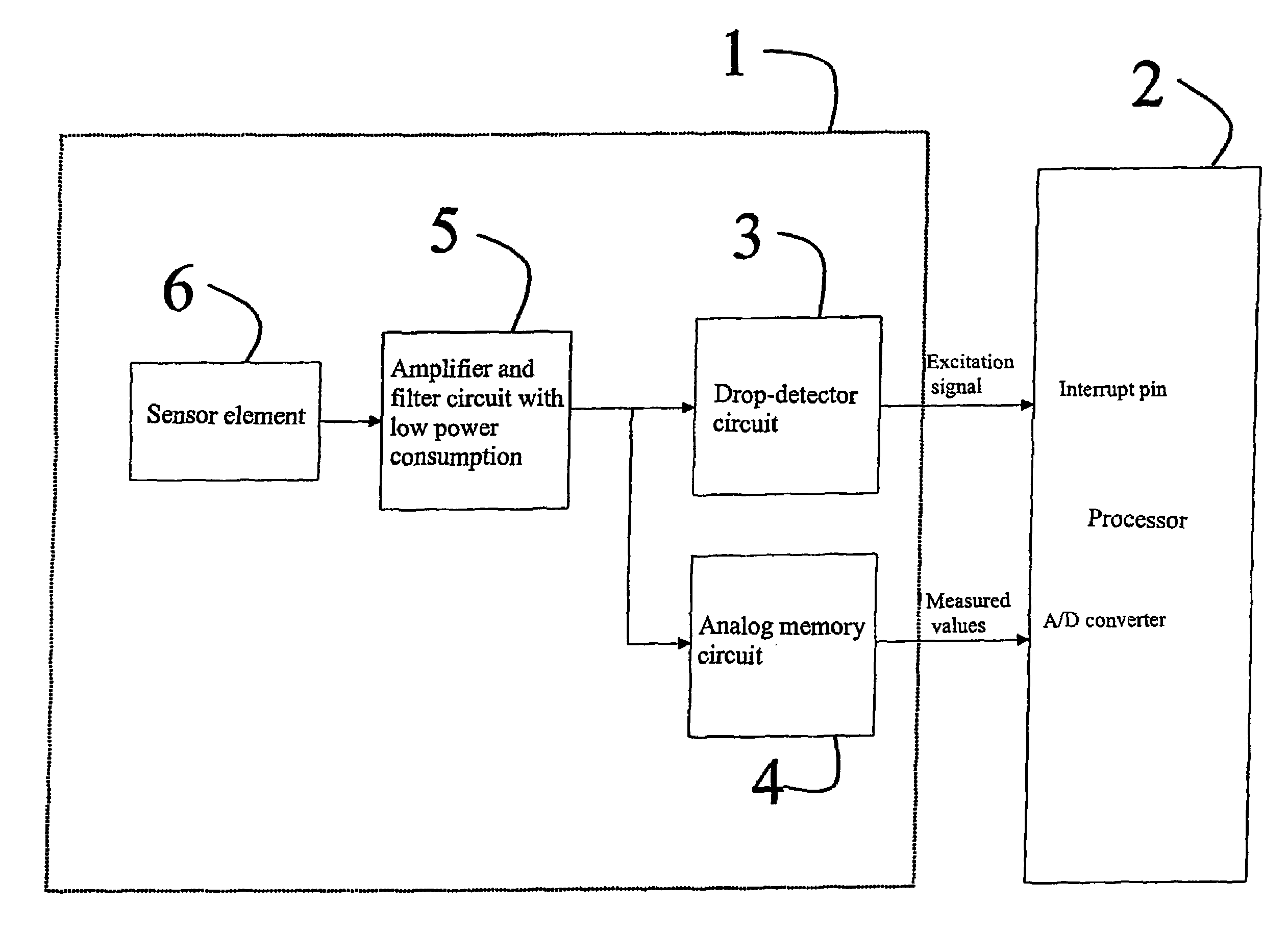
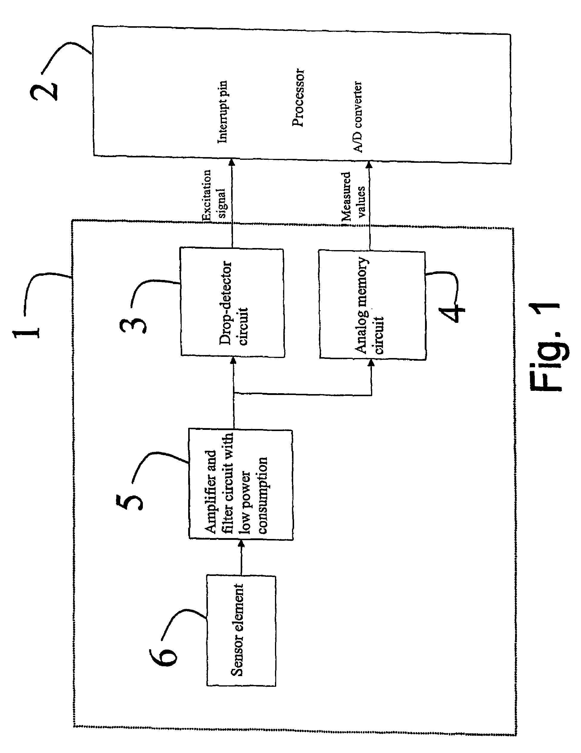
[0021]In the method according to the invention, the power consumption of the sensor is minimized by dividing the measuring electronics into two parts, according to FIG. 1:[0022]a detection circuit 1, which is switched on the whole time, and[0023]a processing circuit 2, which is normally kept switched off in a so-called power-saving mode, and which is excited for measurement only when necessary.

[0024]The detection circuit 1, which is designed to consume as little power as possible, is formed of the actual sensor 6, an amplifier and a filter which can be integrated in the same block 5, and a comparator 3. When a hydrometeor strikes the detector element 6, it creates a signal, which block 5 amplifies and possibly band-pass filters for the frequency range typical of the signal describing it and compares it with the threshold value of the comparator 3. The filtering can, of course, also be high or low-pass filtering, always according to the properties of the spurious signal. If the thres...


PUM


Abstract

This publication discloses a method and apparatus for measuring hydrometeors. According to the method, the mechanical impulses of hydrometers falling on a detection surface are measured. According to the invention, part of the measuring device (1) is used to perform a continuous measurement, in order to define a threshold value for an impulse and only after the threshold value is exceeded is the final part (2) of the measuring apparatus excited for measuring operations, in order to minimize the power consumption of the apparatus.

Description

CROSS-REFERENCE TO RELATED APPLICATION[0001]The present application claims priority under 35 U.S.C. §119 to PCT Application No. FI 2004 / 000372, filed Jun. 16, 2004, the entire contents of which are hereby incorporated by reference.BACKGROUND OF THE INVENTION[0002]1. Field of the Invention[0003]The present invention relates to a methodin connection with a measuring device detecting hydrometeors.[0004]2. Description of Background Art[0005]The invention also relates to an apparatus used in connection with a sensor detecting hydrometeors.[0006]The method to which the invention relates concerns, sensors that measure precipitation is its various forms (especially water, snow, and hail), and which are based on detecting the mechanical impulses created when hydrometeors strike the detector surface. The method is suitable for both sensors, which measure the hydrometeors striking the detector surface directly, and sensors equipped with a funnel-like collector, which measure the water exiting ...

Claims


Application Information

Patent Timeline
IPC IPC(8): G06F19/00G01W1/00G01W1/14
CPCG01W1/14Y02A90/10
Inventor ASPOLA, JUHANIIKONEN, JOUNIKOPSALA, PANUKORVENOJA, JAAKKOSALMI, ATTE
Owner VAISALA
Why Eureka
Try Eureka