
Gravity operated cable brake for an elevator

a gravity-operated, cable-operated technology, applied in the direction of braking systems, elevators, hoisting equipment, etc., can solve the problems of high manufacturing time-consuming installation, and high cost of cable brakes, so as to achieve simple and reliable cable brakes.

Inactive Publication Date: 2007-10-30
INVENTIO AG
View PDF19 Cites 7 Cited by
  • Summary
  • Abstract
  • Description
  • Claims
  • Application Information

AI Technical Summary

Benefits of technology

The gravity-actuated cable brake is reliable, inexpensive, and maintenance-free, with improved trigger release reliability and the ability to reset the brake without external energy, reducing manufacturing and installation costs.

Problems solved by technology

A disadvantage of this equipment is that the cable brake is expensive.
The trigger mechanism, the cam follower and cam surfaces, and the brake enclosure are costly to manufacture and time consuming to install.

Method used


Image

  • Gravity operated cable brake for an elevator
  • Gravity operated cable brake for an elevator
  • Gravity operated cable brake for an elevator

Examples


Embodiment Construction

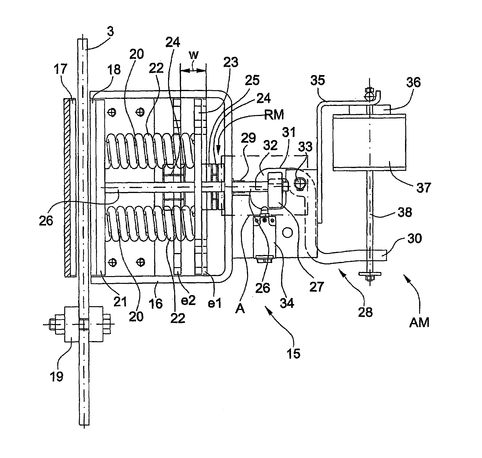
[0015]FIG. 1 is a schematic representation of an elevator installation with a cable brake according to the present invention providing braking security. In a not illustrated elevator shaft, an elevator car 1 with doors 2 is connected by cable strands 3 with a counterweight 4 for vertical movement in the elevator shaft. An electric motor 5 drives a gear mechanism 7 by an input shaft 6. At an output shaft 8 of the gear mechanism 7 is mounted a drive sheave 9 for driving the cable strands 3. The gear mechanism 7 includes a worm 7.1 at the input shaft 6 and a mating gear 7.2 at the output shaft 8. Other mechanism-types like, for example, a crown gear set are also possible. A motor brake 10 is attached to a free end of the input shaft 6.

[0016]At the opposite end of the input shaft 6 is a first encoder 11 for sensing the speed of the input shaft 6. At and end of the output shaft 8 is mounted a second encoder 12 for sensing the speed of the output shaft 8. As a variation, the second encode...


PUM


Abstract

A cable brake has an electromagnet releasably retaining a mass that falls down guide rods under the effect of gravity and impacts a first arm of a trigger lever. Upon impact by the mass, the trigger lever rotates a second arm with a pawl to release a crossbar, whereupon pressure springs press a moveable brake plate against a cable strand to halt the cable strand. A return mechanism utilizes a screw and cooperating nut or a coupler to return the moveable brake plate and pre-stress the pressure springs.

Description

BACKGROUND OF THE INVENTION[0001]The present invention relates to a cable brake for an elevator to halt a cable strand by applying a brake plate on the cable strand, and having a release trigger mechanism to introduce the brake action and apply the braking force of the brake plate, the brake plate being returnable to an initial position after the brake action by a return mechanism.[0002]The patent document EP 0 651 724 B1 shows a cable brake wherein the elevator car supporting cables extend between two brake plates. The one brake plate is connected with the brake enclosure and the other brake plate is moveable. Each of a pair of links has one end pivotally connected with the other brake plate and an opposite end engaging a cam follower. The cam follower is released by an electromagnetic latch controlled by an overspeed governor and rides on a pair of cam surfaces under the force of a pair of springs to move the other brake plate toward the one brake plate to clamp the cables and sto...

Claims


Application Information

Patent Timeline
Patent Type & Authority Patents(United States)
IPC IPC(8): B60T7/12B66B5/24B66B15/00B66D5/16
CPCB66D5/16B66B5/185
Inventor ECKENSTEIN, RUDOLFMARCUZ, CARLOS LATORRE
Owner INVENTIO AG
Features
  • Generate Ideas
  • Intellectual Property
  • Life Sciences
  • Materials
  • Tech Scout
  • Unparalleled Data Quality
  • Higher Quality Content
  • 60% Fewer Hallucinations
Learn More