System and method for detecting customer premise equipment behind a router on a data-over-cable system

a data-over-cable system and customer-premise equipment technology, applied in data switching networks, two-way working systems, instruments, etc., can solve problems such as agent software not knowing whether it should reboo

Active Publication Date: 2007-10-30
AMERICAN TELEPHONE & TELEGRAPH CO
View PDF11 Cites 87 Cited by
  • Summary
  • Abstract
  • Description
  • Claims
  • Application Information

AI Technical Summary

Problems solved by technology

At this point, the agent software does not know whether it should reboot

Method used


Image

  • System and method for detecting customer premise equipment behind a router on a data-over-cable system
  • System and method for detecting customer premise equipment behind a router on a data-over-cable system
  • System and method for detecting customer premise equipment behind a router on a data-over-cable system

Examples


Embodiment Construction

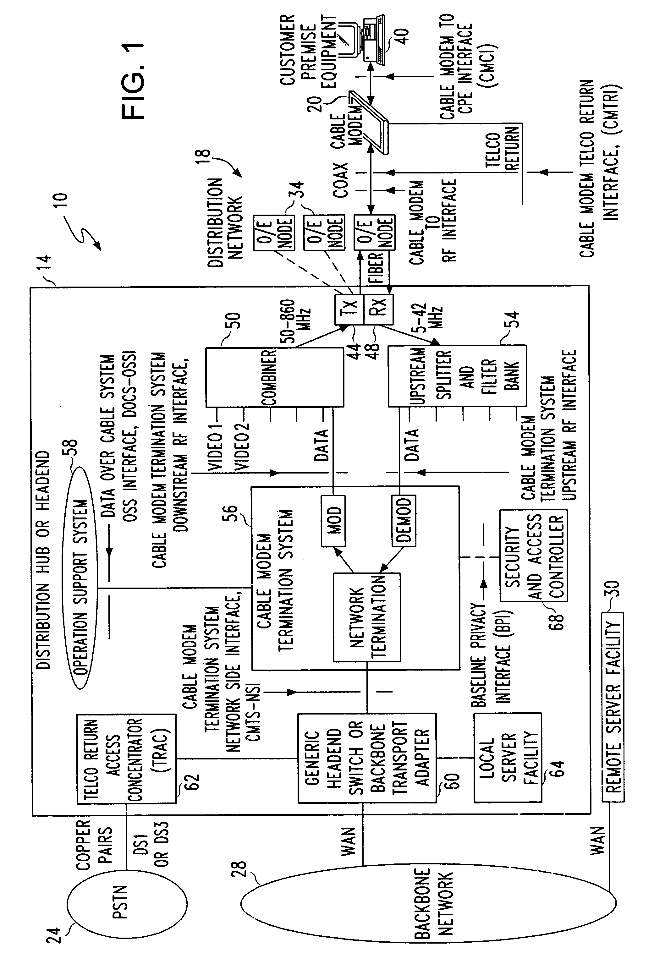
[0038]A data-over-cable system in which the system and method of the present invention may operate is shown in FIG. 1. System 10 includes a distribution hub or head end 14 that is coupled through a distribution network 18 to one or more cable modems 20. Head end 14 may be coupled to public switched telephone (PSTN) 24 and / or backbone network 28. Network 28 couples head end 14 to one or more remote server facilities 30. Backbone network 28 is coupled to head end 14 and remote server facility 30 through any known wide area network (WAN) configuration while copper wire pairs, DS1, or DS2 connections may be used to couple head end 14 to PSTN 24. Head end 14 may be coupled to nodes 34 of distribution network 18 by optical fiber or coaxial cable. Coaxial cable or optical cable may be used to couple nodes 34 to a cable modem 20 at a subscriber site, although most typically coaxial cable is used for such coupling.

[0039]A cable modem 20 at a subscriber site may be used to couple a customer p...


PUM


Abstract

A system and method permits a network management agent executing on a customer premise equipment (CPE) component to determine whether a router is coupled between the CPE component and the cable modem through which the CPE component communicates with a data-over-cable network. The network management agent executing on the CPE component encapsulates the MAC address of the CPE component in a network management message that is sent to a server at the head end of the data-over-cable network. The head end compares the encapsulated MAC address with the MAC address of the device coupled to the cable modem that sent the network management message. If the MAC addresses are not the same, the server at the head end sets a router status element in the network management message response and sends it to the agent executing on the CPE component. The agent may then interrogate the router status element and determine whether a router is coupled between the CPE component on which it is executing and the cable modem through which it is coupled to the data-over-cable network.

Description

FIELD OF THE INVENTION[0001]This invention relates generally to data-over-cable systems and, more particularly, to the Internet Protocol (IP) management of Customer Premise Equipment (CPE) by the Cable Modem Termination System (CMTS) of a Multiple Service Operator (MSO) in data-over-cable systems.BACKGROUND OF THE INVENTION[0002]One of the earliest methods of accessing services available over the Internet was through subscription service provided by an Internet Service Provider (ISP). Most subscribers were individuals who owned personal computers. After obtaining a subscription with an ISP, they would install ISP access software on their computers. This software would use a modem, either internal or external to a computer, to dial an access number for the ISP and establish a communication link with an ISP server through the Public Switched Telephone Network (PSTN). The ISP server could then communicate data messages between the subscriber's computer and other computers coupled to th...

Claims


Application Information

Patent Timeline
IPC IPC(8): G06F15/173G06F15/16H04N7/173H04L12/28
CPCH04L12/2801H04L12/2856H04L41/046H04L12/287H04L12/2861
Inventor KUMAR, SURESH W. G.
Owner AMERICAN TELEPHONE & TELEGRAPH CO
Why Eureka
Try Eureka