Density measuring apparatus containing a densimeter and a method of using the same in a pipeline

a technology of density measurement and density measurement, which is applied in the direction of instruments, specific gravity measurement, process and machine control, etc., can solve the problems of time lag, inability to know whether the density has changed, and not having uniform consistency, so as to achieve easy installation and maintenance, simple and durable structure of density measuring apparatus, and easy calculation of fluid density

Active Publication Date: 2007-11-06
BAKER HUGHES INC
View PDF19 Cites 23 Cited by
  • Summary
  • Abstract
  • Description
  • Claims
  • Application Information

AI Technical Summary

Benefits of technology

[0009]For a pipe section having a known empty weight and a known fluid flow volume, the density of the fluid can be easily calculated based on the weight measured by the weight measuring unit. Because the sample size includes all of the fluid in the second pipe section, localized inconsistencies in the mixture are not reflected in the density measurement. Furthermore, the structure of the density measuring apparatus is simple and durable, making it easy to install and maintain in a variety of applications. Also, the weight measuring unit measures the weight of the second pipe section continuously, eliminating the time delay.

Problems solved by technology

These nuclear densimeters have certain drawbacks, including safety concerns that are always present when working with radioactive materials, and a time lag associated with each density measurement.
This is a disadvantage when using a fluid such as a sand slurry, that may not have uniform consistency.
In that case, it is impossible to know whether the changed density is due to a localized concentration of material or a systemic problem with the fluid composition.
While eliminating the safety concerns associated with nuclear densimeters, U-tube densimeters can still provide misleading results when used with inconsistently mixed fluids.
Furthermore, the additional tubing needed to construct the U-tube presents a disadvantage, especially in an oilfield environment.

Method used


Image

  • Density measuring apparatus containing a densimeter and a method of using the same in a pipeline
  • Density measuring apparatus containing a densimeter and a method of using the same in a pipeline
  • Density measuring apparatus containing a densimeter and a method of using the same in a pipeline

Examples


Embodiment Construction

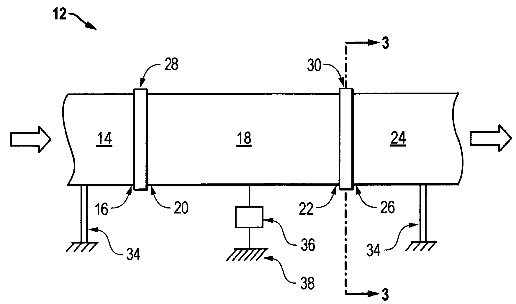
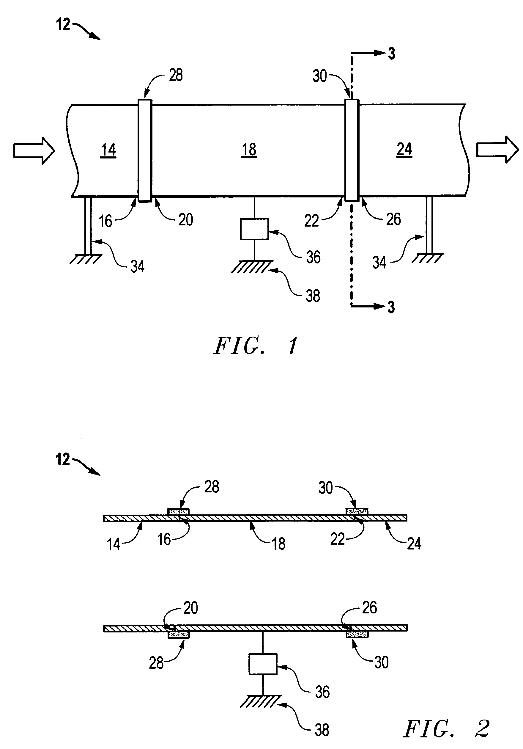
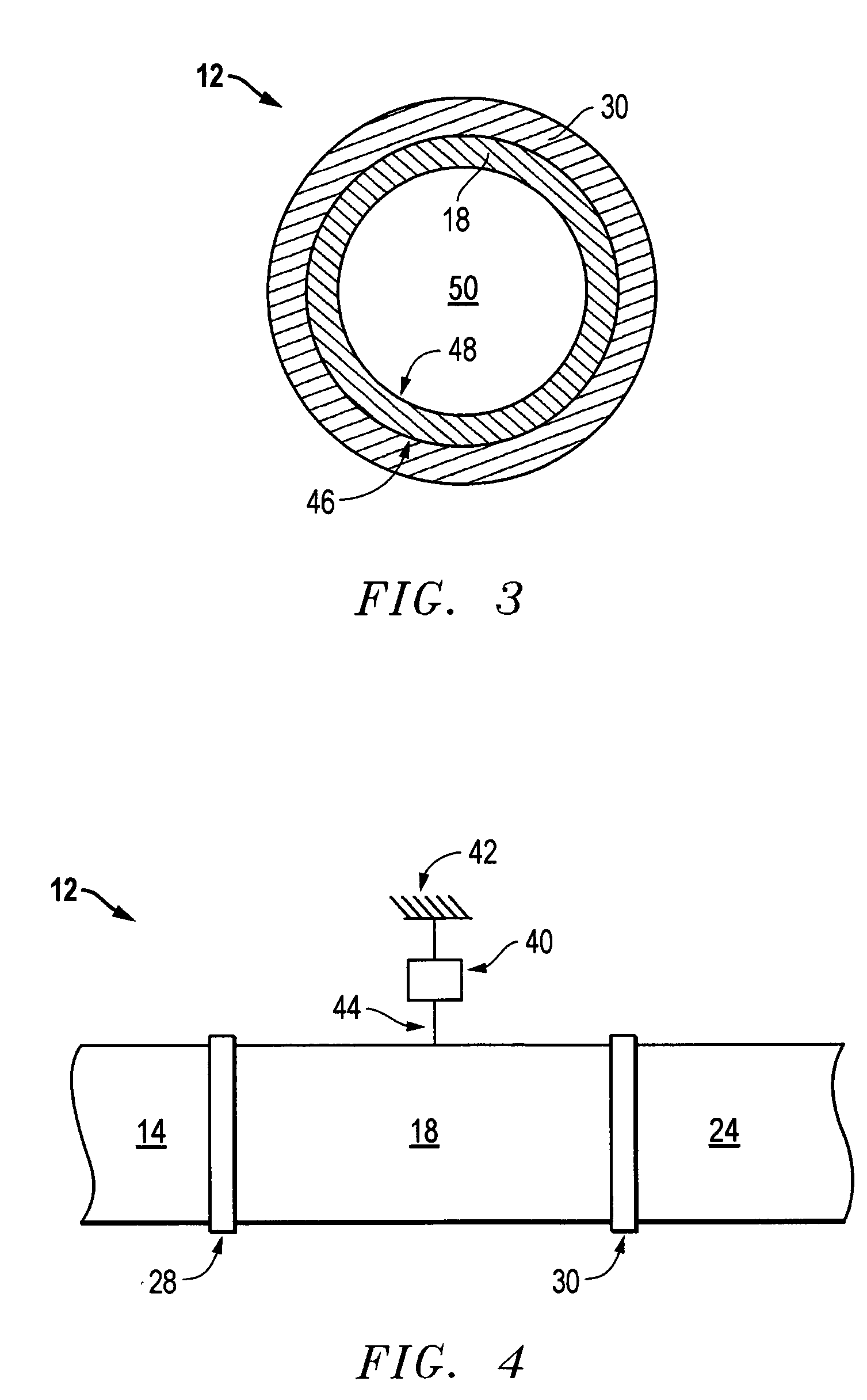
[0020]FIGS. 1-3 have similar elements that are similarly numbered and will be described in conjunction with each other. A pipeline carries a fluid flow in the direction indicated by the arrows in FIG. 1. A densimeter 12 is installed in the pipeline, the densimeter 12 comprising an inlet section 14 having a downstream end 16, a second section 18 having an upstream end 20 and a downstream end 22, and an outlet section 24 having an upstream end 26. A first flexible coupling 28 joins the inlet section downstream end 16 to the second section upstream end 20. A second flexible coupling 30 joins the second section downstream end 22 to the outlet section upstream end 26. The flexible coupling may be any type of flexible connector known in the art, including, without limitation, elastomeric couplings or flexible metal couplings. A preferred embodiment uses part number 208-008 mechanical joint couplings manufactured by John L. Schultz, Ltd.

[0021]An inlet support 32 carries the weight of the i...


PUM

PropertyMeasurementUnit
densityaaaaaaaaaa
distanceaaaaaaaaaa
weight measuringaaaaaaaaaa

Abstract

A densimeter contains an inlet pipe section, a second pipe section joined to the downstream end of the inlet pipe section, and an outlet pipe section joined to the downstream end of the second pipe section. The inlet and outlet pipe sections are constrained by a support structure, while flexible couplings allow the second section of pipe to undergo a limited amount of radial motion relative to the adjacent pipe sections. The weight of the second pipe section is supported by a weight measuring unit, which continuously measures the weight of the second pipe section as fluid flows through the densimeter. One preferred embodiment of the invention uses the densimeter to measure the density of a proppant in a blender system for preparing fluid mixtures for fracturing and propping oil bearing geological formations.

Description

FIELD OF THE INVENTION[0001]The present invention relates generally to a density measuring apparatus for measuring the density of a fluid flowing continuously through a pipeline, and a method of using the same. In a preferred embodiment, the density measuring apparatus of the invention is used to measure the density of a proppant slurry in a blender system for preparing fluid mixtures for fracturing and propping oil bearing geological formations.BACKGROUND OF THE INVENTION[0002]Fracturing and propping an oil well is a well known process in which fluid, generally water or oil, is pumped into an oil well at high flow rates (typically 200 to 5000 gallons per minute) and high pressures to hydraulically fracture the underlying oil bearing formation. The fluid is combined with any number of chemicals to produce certain fluid properties. Generally the fluid is mixed with certain polymers to increase its viscosity and allow it to transport a proppant into the fracture created. The fluid is ...

Claims


Application Information

Patent Timeline
Patent Type & Authority Patents(United States)
IPC IPC(8): G01N9/02
CPCB01F3/12B01F13/0035B01F15/00207G05D11/137G01N9/04B01F15/00246B01F2215/0081B01F23/50B01F33/502B01F35/2136B01F35/213B01F2101/49
Inventor BURNETTE, BLAKECARLSON, BRADLEY T.WADE, DON
Owner BAKER HUGHES INC
Why Eureka
Try Eureka