Layout of the top part of an aircraft cabin

a top part and aircraft cabin technology, applied in the direction of aircraft crew accommodation, bedstands, seating arrangements, etc., can solve the problem of providing a large number of beds, and achieve the effect of freeing up maximum space for passengers

Active Publication Date: 2007-11-06
AIRBUS
View PDF14 Cites 19 Cited by
  • Summary
  • Abstract
  • Description
  • Claims
  • Application Information

AI Technical Summary

Benefits of technology

[0018]To free up maximum space for the passengers on the beds, passage ways for

Problems solved by technology

The problem is to be able to p

Method used


Image

  • Layout of the top part of an aircraft cabin
  • Layout of the top part of an aircraft cabin
  • Layout of the top part of an aircraft cabin

Examples


illustration 3

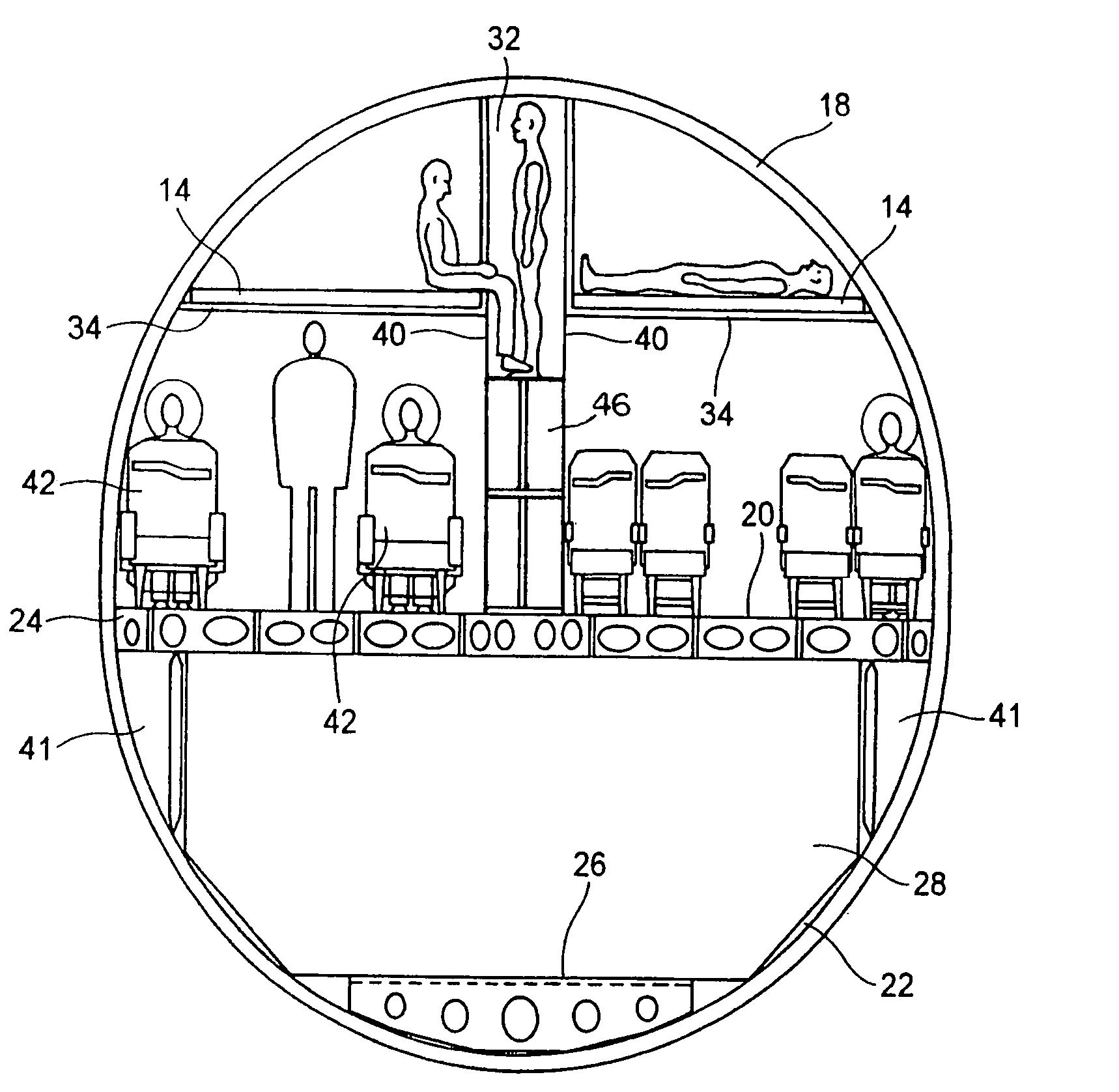
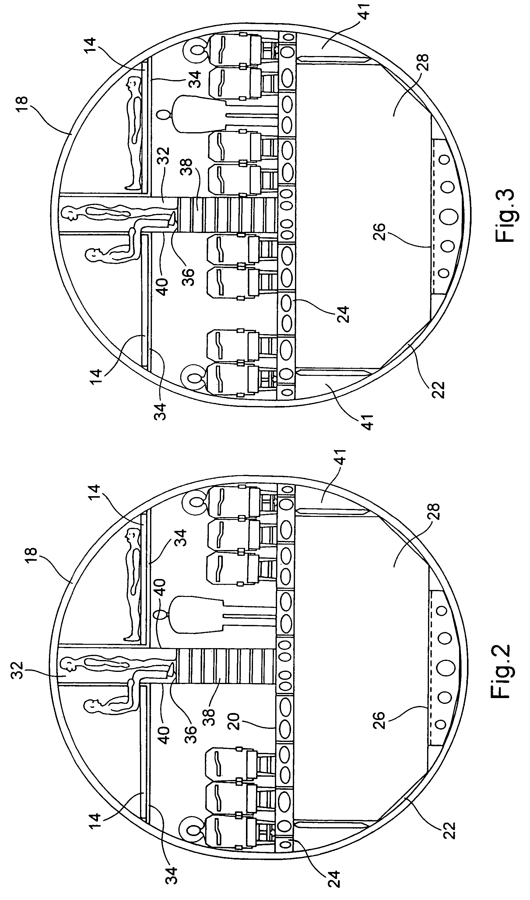
[0035]Illustration 3 shows a variation of the design of illustration 2. The difference here is that there are three front seats on each side of central aisle 32 at the level of bridge 20 while, as can be seen on the drawing, there are four in the configuration of illustration 2.

[0036]The configuration shown on illustration 4 is original by the fact that convertible seats 42 are located on one side of central aisle 32 while on the other side of this central aisle, there are seats 12 corresponding to the seats that are usually found in the coach section compartments. In general, in a plane with a single bridge, the seats for the coach class are arranged in the back of the cabin while the first and business classes are arranged in the front of the cabin. Here, first class and business class passengers are located to the right of the plane, with respect to the direction of operation of the plane (in other words, to the left on illustration 4) and the coach class passengers to the left o...


PUM


Abstract

An aircraft cabin that includes a main structure being the structure of the aircraft and enclosing the cabin; a bridge forming a flat surface on which the seats are secured; an aisle extending longitudinally in cabin and elevated with respect to bridge, and beds or cots accessed by said aisle and arranged above seats of bridge, transversally with respect to aisle and on both sides of such aisle.

Description

CROSS REFERENCE TO RELATED APPLICATIONS[0001]This application is based upon and claims priority under 35 U.S.C. §119 from French Patent Application No. 0408239, filed Jul. 26, 2004 and under 35 U.S.C. §119(e) from U.S. Provisional Application No. 60 / 606,522, filed Sep. 2, 2004.BACKGROUND OF THE INVENTION[0002]This invention involves the layout of the top part of an aircraft cabin.[0003]The technical domain of the invention involves the transportation of passengers in an airplane. In a given space, the cabin of an airplane, as many passengers as possible must be placed while giving them optimal comfort. Usually, three classes of comfort are offered: first class, business class and coach. In first class and business class, the seats offered to the travelers are most often convertible seats that offer in an initial position, a seat to the passenger and in another position, a cot or bed, more or less inclined in business class. Various solutions are known for this state of the art to pr...

Claims


Application Information

Patent Timeline
IPC IPC(8): B64D11/06
CPCB64D11/0601B64D11/00B64C2001/0027B64D2011/0084
Inventor SAINT-JALMES, BRUNOREZAG, ANDREZANEBONI, JAZON
Owner AIRBUS
Why Eureka
Try Eureka