Full history time-temperature indicator system

a technology of indicator system and full history, applied in the direction of time interval measurement without driving mechanism, time interval measurement, chemical analysis using precipitation, etc., can solve the problem of deterioration process faster, deterioration of perishable goods at high temperatures, and danger of propagation of microorganisms injurious to human health or spoilage of organisms

Inactive Publication Date: 2007-11-06
TIMETEMP
View PDF44 Cites 51 Cited by
  • Summary
  • Abstract
  • Description
  • Claims
  • Application Information

AI Technical Summary

Benefits of technology

[0013]Accordingly, the invention relates in a first aspect to a full-history time-temperature indicator system which is capable of exhibiting a time-temperature dependent and visually detectable chemical reaction. The system comprises at least one immobilized and at least one mobile reactant, wherein the reactants are contained in separate adjacent compartments, and the reactants initially are separated by a sealing to prevent contact between the reactants. The rate of mobility of the mobile reactant is time-temperature dependent and the system is activatable by removing the sealing between the compartments whereby the mobile reactant in a time-temperature dependent manner is brought into contact with the immobilized reactant, resulting in a visually detectable reaction signal that indicates the time-temperature history.

Problems solved by technology

The deterioration processes are faster when the temperature is raising due to increasing biochemical reaction rates, and therefore the quality of perishable goods declines more rapidly at high temperatures than at low temperatures.
If such products are not stored under appropriate temperature conditions then there is a danger of propagation of microorganisms which are injurious to human health or of spoilage organisms.
By date marking only, no information is given to the consumer or others about the storage conditions to which the product has been exposed, hence the purchasers of susceptible products are not able to determine whether the product has been stored under appropriate temperature conditions during the time of storage.
The end consumer will e.g. not be able to determine if a frozen product has been thawn during transportation and subsequently frozen before being put on sale.

Method used


Image

  • Full history time-temperature indicator system
  • Full history time-temperature indicator system
  • Full history time-temperature indicator system

Examples


example 1

Preparation of the Mobile and the Immbolized Reactant

[0045]The mobile reactant is a 0.1M solution of K4Fe(CN)6 in a mixture of 0.64% (w / w) alginate, 47.29% (w / w) glycerol, 52.06% (w / w) water.

[0046]The immobilized reactant is prepared by slowly adding a 0.1 M FeCl3 solution in a mixture of 47% (w / w) glycerol and 53% (w / w) water to a mixture of 0.64% (w / w) alginate, 47.29% glycerol and 52.06% (w / w) water. The amount of 0.1 M FeCl3 solution is 17% (w / w) of final weight. The mixing is done at room temperature by stirring vigorously. By this method a viscous liquid is achieved wherein small gel lumps containing immobilized Fe3+ are equally dispersed.

example 2

Time-temperature Indicator Prepared as an Ampoule

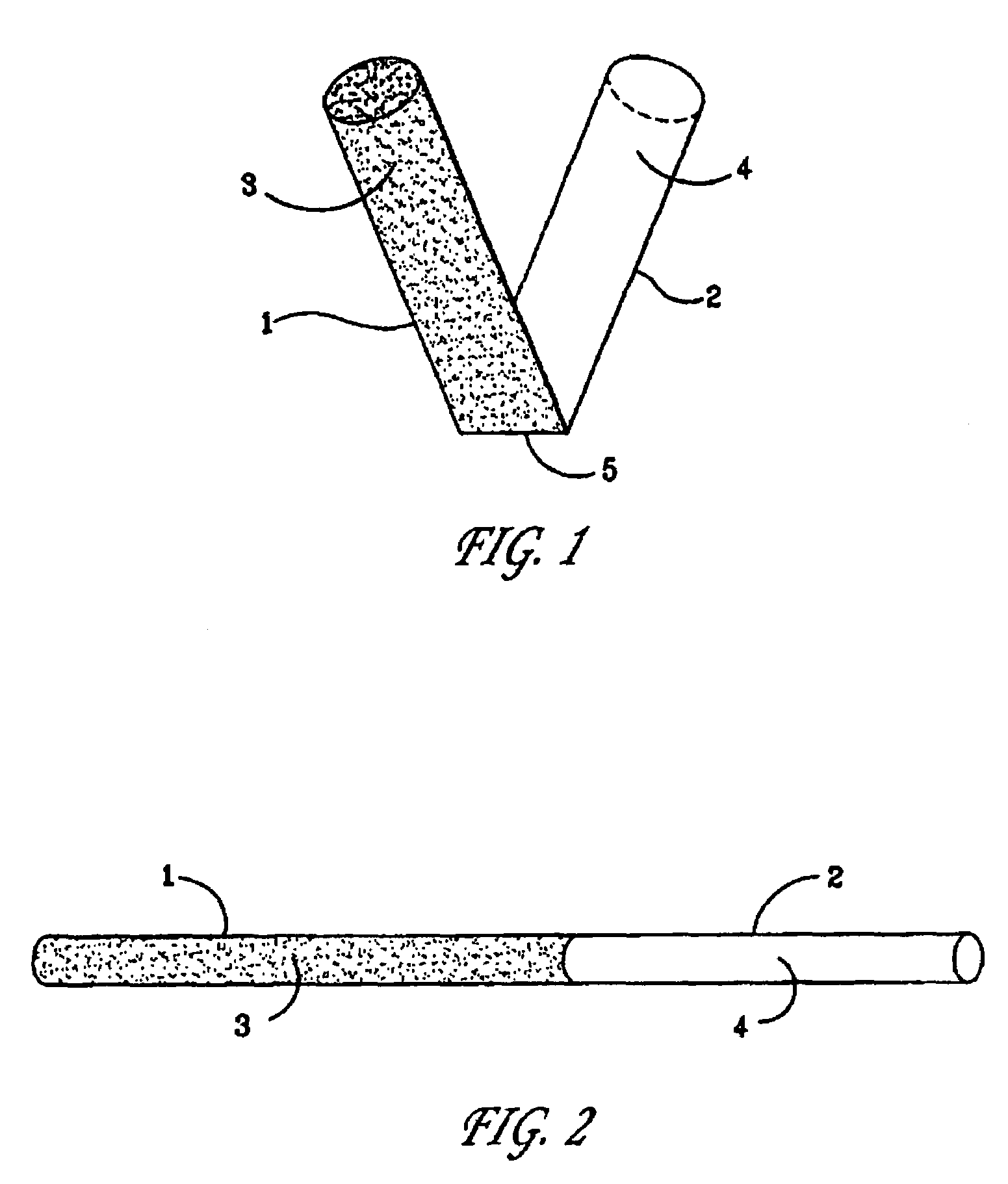
[0047]For preparing a time-temperature indicator as an ampoule, two transparent cylinders made of polystyrene, each of them closed in one or the ends were applied. One of the cylinders (No. 1) was able to fit into the other cylinder (No. 2) by having an outer diameter which was equal to the inner diameter of cylinder No. 2.

[0048]The mobile reactant was prepared as described in Example 1 and contained K4Fe(CN)6 at a concentration of 0.1 M. The mobile reactant was transferred to cylinder No. 1.

[0049]The immobilized reactant containing Fe3+ ions immobilized in the alginate gel was prepared as described in Example 1 and subsequently transferred to cylinder No. 2.

[0050]The two cylinders were assembled by gently pressing them together, carefully avoiding formation of air bubbles in the cylinders, and by this the chemical reaction was started.

[0051]The time-temperature indicator was incubated and regularly inspected for coloration of the gel...

example 3

Colour Development as Function of Time at 4° C. in a Strip Shaped Time-temperature Indicator

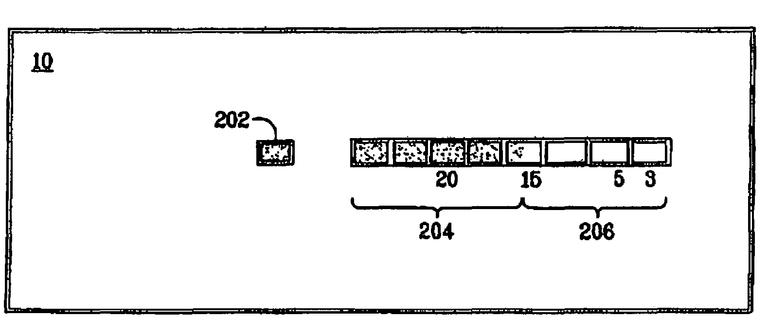
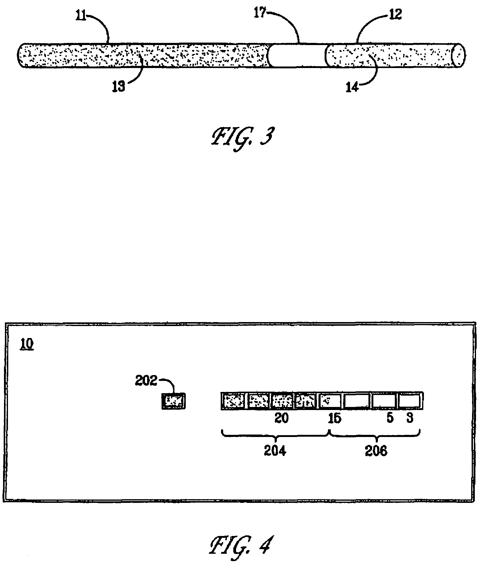
[0052]A time-temperature indicator was prepared as a strip wherein the reactants were prepared as described in the above example 1.

[0053]The colour development in the part of the strip-shaped time-temperature indicator containing the immobilized Fe3+ was monitored. The colour development was measured in percentages as the length of the strongly blue coloured zone compared to the total length of the part of the time-temperature indicator containing the immobilized reactant. The time-temperature indicator was kept at a constant temperature of 4° C. for 76 days.

[0054]The results of the above experiment is presented in the below Table 3.1.

[0055]

TABLE 3.1DaysColour development (%)001950387557887693

[0056]It is apparent from the above results that the time-temperature indicator responds well to the exposure of time at a constant temperature.


PUM

PropertyMeasurementUnit
temperatureaaaaaaaaaa

Abstract

A full-history time-temperature indicator system which is capable of exhibiting a time-temperature dependent and visually detectable chemical reaction, useful for monitoring the time and temperature exposure of food products. The system comprises an immobilized reactant, such as Fe3+, and a mobile reactant, such as Fe(CN)64-, initially contained in separate compartments, and separated by a sealing. The system is activated by removing a sealing between the compartments whereby the mobile reactant in a time-temperature dependent manner is brought into contact with the immobilized reactant resulting in a visually detectable reaction signal.

Description

This application is a 35 U.S.C. § 371 of International Application No. PCT / IB00 / 01443 filed Oct. 9, 2000, which claims priority from Denmark patent application PA 1999 01450, filed Oct. 11, 1999.FIELD OF INVENTION[0001]The invention pertains to the provision of a time-temperature indicator system useful for monitoring the environmental exposure of products that undergo progressive quality changes in response to such exposures. In particular there is provided a full-history time-temperature indicator system for the cumulative monitoring of the time and temperature exposure of especially perishable products.TECHNICAL BACKGROUND AND PRIOR ART[0002]The quality of food products and other perishables are highly dependent on storage conditions such as the temperature and the storage time from production or packing until it finally reaches the end consumer. The deterioration processes are faster when the temperature is raising due to increasing biochemical reaction rates, and therefore the ...

Claims


Application Information

Patent Timeline
Patent Type & Authority Patents(United States)
IPC IPC(8): G01K3/04G01K11/12C09K9/00G01N31/00G01N31/02G01N31/22G04F1/00
CPCG01N31/229G01K3/04
Inventor SKJERVOLD, PER OLAVSALBU, BRITHEYERDAHL, PETTER HIERONYMUSLIEN, HELGE
Owner TIMETEMP
Why Eureka
Try Eureka