Winged angled needle assembly

a needle and angled technology, applied in the direction of infusion needles, intravenous devices, infusion devices, etc., can solve the problems of affecting the flow of therapeutic fluid, the internal diameter of the cannula is often decreased, etc., and achieve the effect of reducing the internal diameter

Inactive Publication Date: 2007-11-06
KAWASUMI LABORITORIES INC
View PDF6 Cites 17 Cited by
  • Summary
  • Abstract
  • Description
  • Claims
  • Application Information

AI Technical Summary

Benefits of technology

[0017]It is an object of the present invention to provide a winged angled needle assembly that can overcome the above various problems of conventional winged angled needle assemblies, for example, the problems that the therapeutic application is often restricted, since the length of a angled needle is determined and limited by the size of wing portions, thereby handling of a winged angled needle assembly is made difficult, that is, when a needle is tightly forced into an implanted port, the infusion of a therapeutic fluid is impaired if a flexible angled needle such as the cannula becomes kinked when extremely curved. And the infusion of a therapeutic fluid is liable to be blocked, since the cannula is often decreased in internal diameter, due to a repulsive pressure exerted by the implanted port formed from an elastomeric material such as a silicone rubber, or the like.

Problems solved by technology

And the infusion of a therapeutic fluid is liable to be blocked, since the cannula is often decreased in internal diameter, due to a repulsive pressure exerted by the implanted port formed from an elastomeric material such as a silicone rubber, or the like.

Method used


Image

  • Winged angled needle assembly
  • Winged angled needle assembly
  • Winged angled needle assembly

Examples


Embodiment Construction

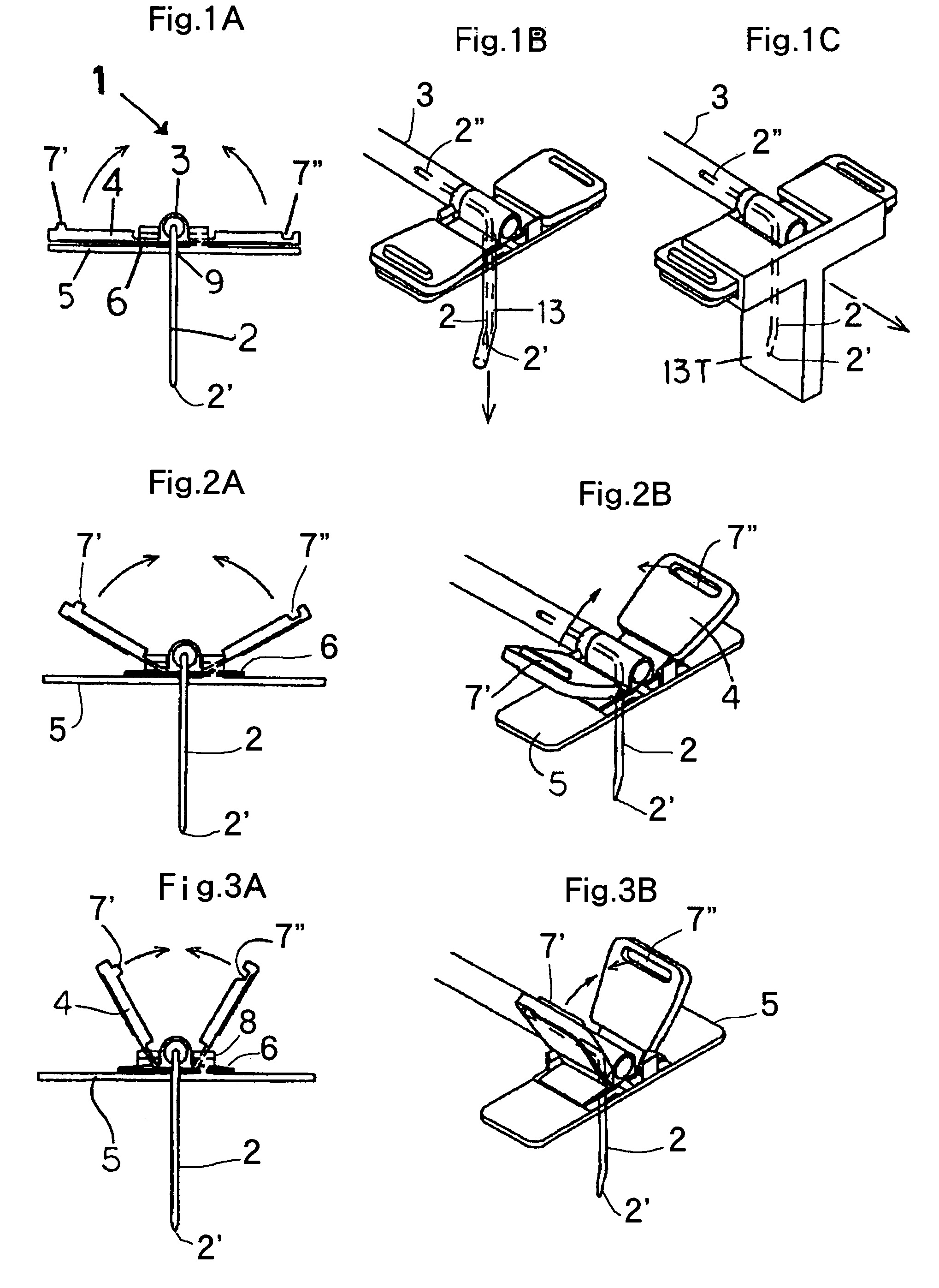
[0045]The present invention will be explained below with reference to drawings. FIGS. 1 to 9 show a preferred embodiment of the winged angled needle assembly of the present invention.

[0046](Basic Constitution of Winged Angled Needle Assembly of the Present Invention)

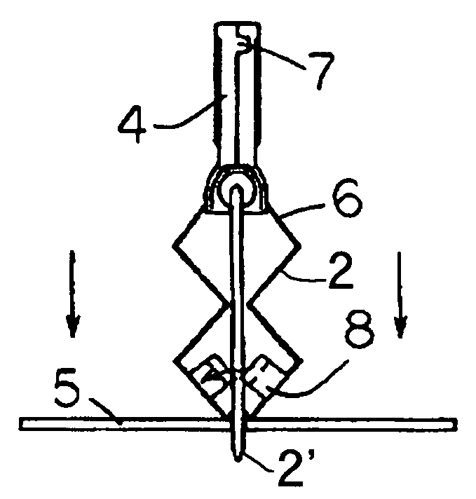
[0047]As shown in the drawings, the winged angled needle assembly or device 1 of the present invention has a hub (or support) 3 to which the proximal end portion 2′ of an angled needle 2 having a sharpened tip portion 2′ is joined and a pair of wings 4 attached to both side potions of the hub 3.

[0048]As shown, for example, in FIG. 1A, the above winged angled needle assembly 1 has a fixing member 5 attached so as to support the above wings 4 and an extendable and contractible needle guard or needle protective shield 6 disposed between the above hub 3 and the above fixing member 5 so as to connect these two members, the hub 3 and fixing member 5.

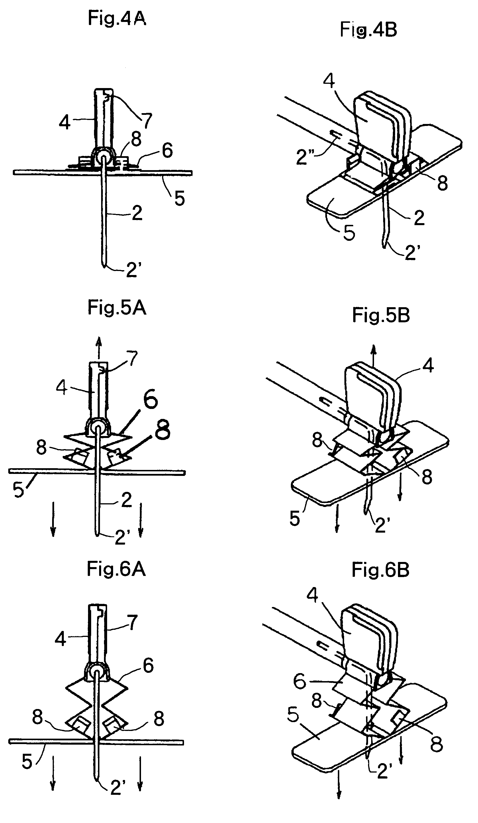
[0049]FIGS. 5 to 9 show the process of pulling the angled needle 2 out of an i...


PUM


Abstract

A winged angled needle assembly has a hub to which a proximal end portion of an angled needle having a sharpened tip portion is joined and a pair of wings attached to both sides of the hub and further includes a fixing member attached so as to support the wings and an extensible, contractible needle guard disposed between the hub and the fixing member so as to connect these two members. The guard extends in the direction from the proximal end portion to the sharpened tip portion of the angled needle when extended, so that the tip portion can be encased in said guard simultaneously with pulling the angled needle out of an implanted port. The guard has an exposure prevention mechanism attached thereto and is externally stopped, so that the sharpened tip portion is kept from exposing once it is encased in the guard. The angled needle can have a length as required regardless of the length of the wings. The fixing member supports the wings opened to be coplanar with each other, serves to stably fix the winged angled needle assembly to an implanted port in an installed state and also works as a support for pulling the angled needle out of the port, so that the winged angled needle assembly can minimize the mental stress of a patient.

Description

BACKGROUND OF THE INVENTION[0001]1. Field of the Invention[0002]The present invention relates to a winged angled needle assembly for constituting a port access infusion set, called PAIS) to be used for blood dialysis, fluid infusion, blood infusion, etc., and it relates particularly to a winged angled needle assembly improved in the form of a protective portion.[0003]For effecting blood dialysis, blood filtering, blood infusion, fluid infusion or the delivery of a therapeutic fluid such as an anticancer medication, insulin, or the like into a vascular system for a long period of time, there has been developed an advanced method in which an implanted port (subcutaneous implanted part) is provided under the surface of the skin of a patient and an angled needle is caused to subcutaneously pierce the implanted port, in place of a conventional direct subcutaneous delivery of the blood system of a patient. PAIS is a device for use in a method using the above implanted port. The winged ang...

Claims


Application Information

Patent Timeline
Patent Type & Authority Patents(United States)
IPC IPC(8): A61M5/00
CPCA61M5/158A61M2005/1581A61M5/3275
Inventor ONO, SEIICHI
Owner KAWASUMI LABORITORIES INC
Why Eureka
Try Eureka