
Detecting molecular binding by monitoring feedback controlled cantilever deflections

a technology of cantilever deflection and molecular binding, which is applied in the field of analyte detection and/or identification, can solve the problems of low sensitivity of the assay, unacceptably high false positive or false negative levels of antibody based assays, and the inability to detect molecular binding,

Inactive Publication Date: 2007-11-06
INTEL CORP
View PDF29 Cites 19 Cited by
  • Summary
  • Abstract
  • Description
  • Claims
  • Application Information

AI Technical Summary

Benefits of technology

This approach provides highly sensitive and selective detection of analytes, reducing mechanical stress on cantilevers and extending their lifespan, while allowing for real-time analysis without washing steps, enhancing the accuracy and reliability of analyte identification.

Problems solved by technology

Antibody based assays may occasionally show unacceptably high levels of false positive or false negative results, due to cross-reactivity of the antibody with different antigens, low antigenicity of the target analyte (leading to low sensitivity of the assay), non-specific binding of antibody to various surfaces, etc.
Problems with sensitivity and / or specificity of such assays may arise.
Nucleic acid hybridization may occur between sequences that are not precisely complementary through mismatch hybridization, leading to false positive results.
As with the techniques discussed above, selectivity and / or sensitivity problems may arise with any standard detection technique.

Method used


Image

  • Detecting molecular binding by monitoring feedback controlled cantilever deflections
  • Detecting molecular binding by monitoring feedback controlled cantilever deflections
  • Detecting molecular binding by monitoring feedback controlled cantilever deflections

Examples


example 1

Charge-Magnet Balanced Cantilever

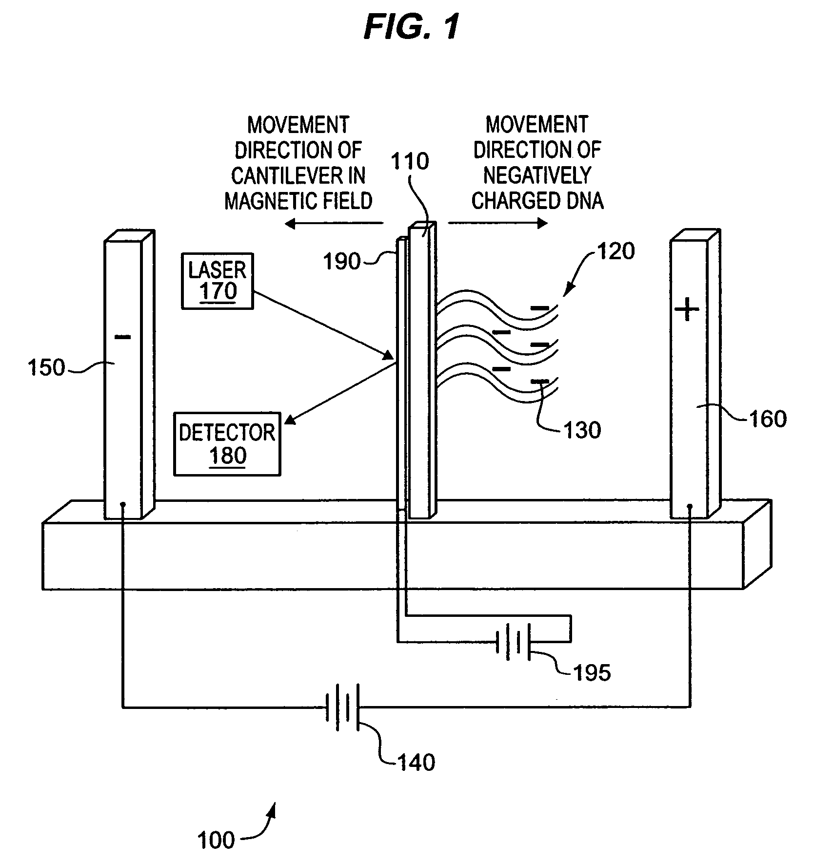
[0096]FIG. 1 illustrates an exemplary apparatus 100 and method for analyte 130 detection and / or identification. The apparatus 100 comprises one or more cantilevers 110 attached to one or more probe molecules 120. The probe molecules 120 bind to electrically charged target analytes 130. An electrical potential gradient is imposed by a direct current power supply 140 attached to a pair of electrodes 150, 160 flanking the cantilever 110. Upon binding of a charged target analyte 130, the cantilever 110 will be deflected towards one electrode 150 or the other 160. In certain embodiments of the invention, the electrodes 150, 160 may be used to initially control movement of analytes 130 toward the probe molecules 120. After analytes 130 have bound to the probes 120, unbound analytes 130 may be moved away from the. cantilever 110 (e.g., by washing the unbound analytes away using an appropriate buffer). Once probes 120 have bound to analytes 130, the electrod...

example 2

Charge-Balanced Cantilever

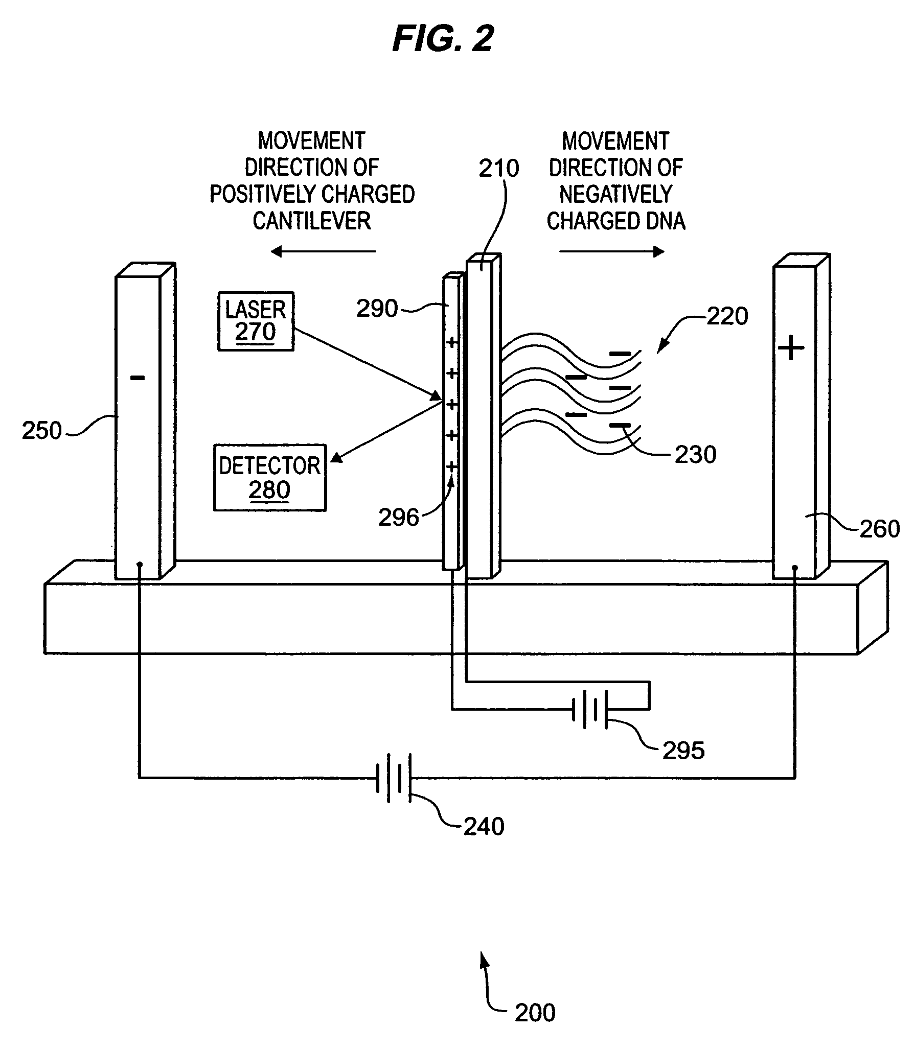
[0101]FIG. 2 illustrates an alternative exemplary apparatus 200 and method for analyte 230 detection and / or identification. The apparatus 200 comprises a cantilever 210 attached to one or more probe molecules 220 that can bind to charged or neutral analytes 230. Binding of charged analytes 230 results in deflection of the cantilever 210 in response to an electrical potential gradient imposed by a first power supply 240 attached to a pair of electrodes 250, 260. Binding of neutral analytes 230 may cause cantilever 210 deflection due to a change in surface tension. Cantilever 210 deflection may be detected by a detection unit comprising a laser 270 and position sensitive photodetector 280.

[0102]In the exemplary embodiment of the invention illustrated in FIG. 2, the counterbalancing force is provided by an inducible charge storage layer 290 attached to or incorporated in the cantilever 210. The charge storage layer 290 comprising, for example, a thin layer of ...

example 3

Cantilever Balanced by Radiation Pressure

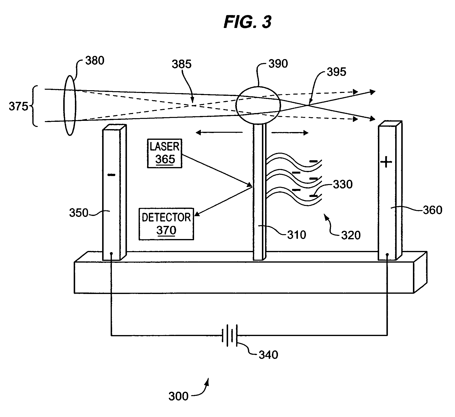
[0103]The use of electromagnetic (e.g., light) radiation to apply a force to various objects is known, for example in the construction and use of optical tweezers (e.g., Walker et al., FEBS Lett. 459:39-42, 1999; Bennink et al., Cytometry 36:200-208, 1999; Mehta et aL., Science 283:1689-95, 1999; Smith et al., Am. J. Phys. 67:26-35, 1999). FIG. 3 illustrates another exemplary apparatus 300 and method for analyte 330 detection and / or identification.

[0104]Alternative geometries are available to provide a radiation pressure counterbalancing force. In embodiments of the invention exemplified in FIG. 3, a transparent object with a curved surface (e.g., a bead 390) and a refractive index that differs from the surrounding medium may be attached to any part of a cantilever 310. A focused light beam 375 can create a force on the transparent object 390 to generate a counterbalancing force. In alternative embodiments of the invention, a light beam 375 m...


PUM

PropertyMeasurementUnit
thickaaaaaaaaaa
thickaaaaaaaaaa
thicknessaaaaaaaaaa

Abstract

The present methods and apparatus concern the detection and / or identification of target analytes using probe molecules. In various embodiments of the invention, the probes or analytes are attached to one or more cantilevers. Binding of a probe to an analyte results in deflection of the cantilever, detected by a detection unit. A counterbalancing force may be applied to restore the cantilever to its original position. The counterbalancing force may be magnetic, electrical or radiative. The detection unit and the mechanism generating the counterbalancing force may be operably coupled to an information processing and control unit, such as a computer. The computer may regulate a feedback loop that maintains the cantilever in a fixed position by balancing the deflecting force and the counterbalancing force. The concentration of analytes in a sample may be determined from the magnitude of the counterbalancing force required to maintain the cantilever in a fixed position.

Description

[0001]This application is a divisional application of U.S. application Ser. No. 10 / 667,776 filed Sep. 22, 2003, now U.S. Pat. No. 7,105,301 which is a continuation-in-part application of U.S. application Ser. No. 10 / 254,201 filed Sep. 24, 2002, now pending. The disclosure of each of the prior applications is considered part of and is incorporated by reference in the disclosure of this application.BACKGROUND OF THE INVENTION[0002]1. Field of the Invention[0003]The methods and apparatus 100, 200, 300 described herein relate to the field of analyte detection and / or identification. In particular, the disclosed methods and apparatus 100, 200, 300 relate to the use of feedback-controlled cantilever 110, 210, 310, 400, 510 deflection for analyte detection and / or identification.[0004]2. Related Art[0005]Various methods have been used for detection and / or identification of biomolecule analytes, such as proteins, peptides, receptors, nucleic acids, hormones, metabolites, etc. Antibody based a...

Claims


Application Information

Patent Timeline
Patent Type & Authority Patents(United States)
IPC IPC(8): C12Q1/68G01N33/543
CPCC12Q1/6825G01N33/54373B82Y5/00Y10S977/924G01N2800/52C12Q2565/501
Inventor SU, XINGCHAN, SELENAKOO, TAE-WOONGYAMAKAWA, MINEOBERLIN, ANDREW A.
Owner INTEL CORP
Learn More