Moisture detection sensor tape with leak locate

a technology of moisture detection and leak location, applied in the direction of fluid tightness measurement, instruments, structural/machine measurement, etc., can solve the problems of expensive problems, metal or plywood roof decking and rafters, and roof leakage costs homeowners, commercial property owners and property insurers hundreds of millions of dollars

Active Publication Date: 2007-11-06
DETEC SYST
View PDF14 Cites 57 Cited by
  • Summary
  • Abstract
  • Description
  • Claims
  • Application Information

AI Technical Summary

Benefits of technology

[0012]It is an object of the present invention to address one or more of the above issues and provide a reliable detection and location system.
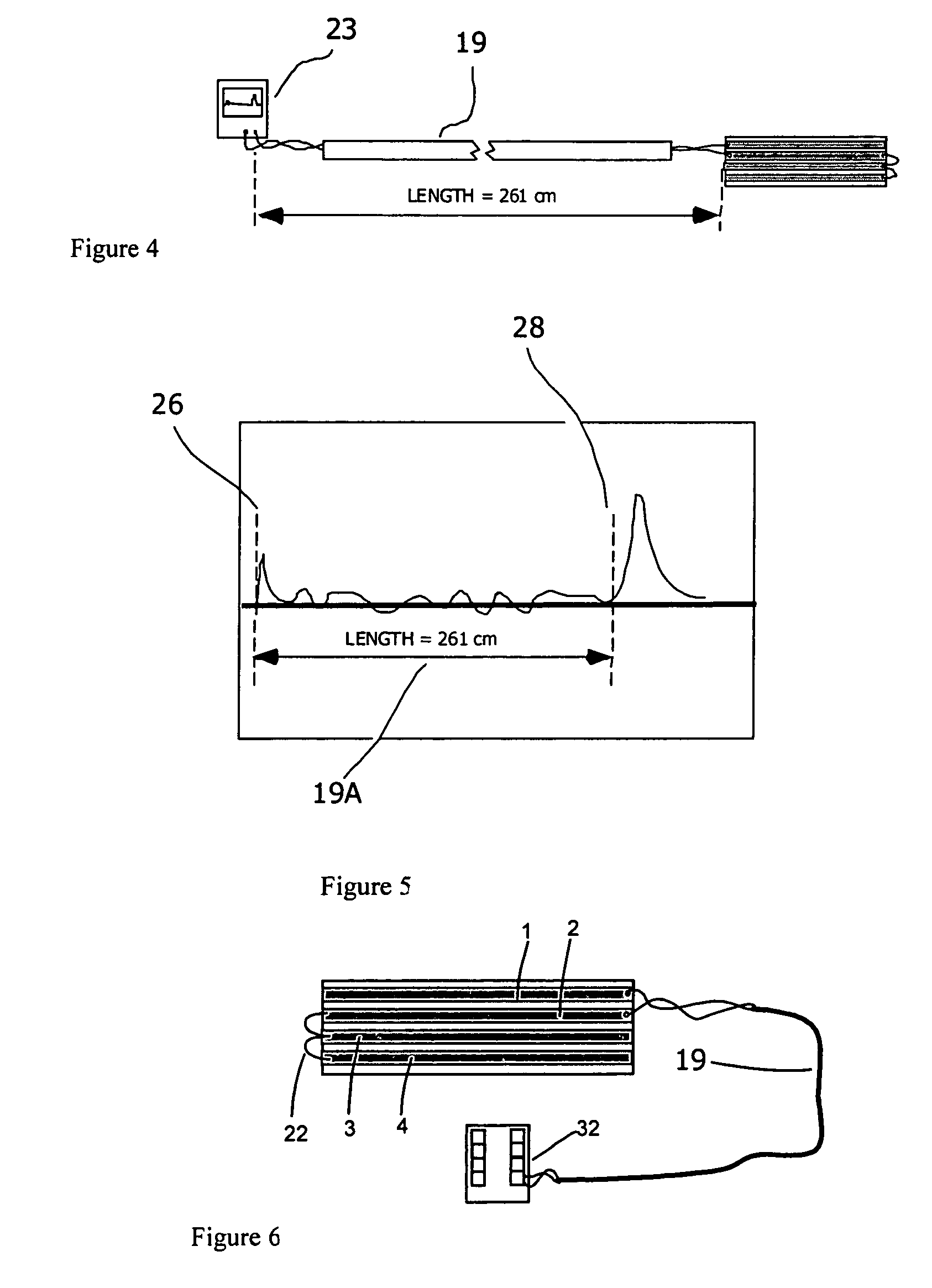
[0044]To provide this useful distance measurement function it is necessary to deliberately design the moisture detection conductors with significantly different characteristic impedance than that of the connecting cable pair. This will ensure a strong reflection and accurate distance measurement to the conductor pair / detection conductors splice point.
[0057]The high frequency impedance of a typical communication or data cable pair is about 100 ohms. To ensure a strong reflection at the cable pair and detection conductor splice point, the impedance of the detection conductor pair must be measurably different than that of the cable pair. From equation (3) this is accomplished by adjusting the UC ratio to achieve the desired results. The high frequency impedance of the detection conductors should be about double that of the cable pair. This will result in a reflection coefficient of ⅓ or better. Approximately ⅓ of the incident pulse will be reflected back from the cable pair and detection conductors splice point thus providing a clear signature for an accurate measurement of the cable pair length.

Problems solved by technology

Leaking roofs cost homeowners, commercial property owners and property insurers hundreds of millions of dollars every year.
Even the smallest leaks can cause expensive problems.
Structural damage to metal or plywood roof decking and rafters due to rot and rust has been commonplace for decades.
Black mold or toxic mold that grows in the wet roof and wall areas is known to cause severe physical problems for occupants as well as severe fiscal problems for builders and insurance companies.
While offering simplicity and limiting the building height, they are also the most difficult to seal and drain.
While providing many benefits, a green roof system further complicates roof problems.
A leak can be difficult to locate and can lead to the dig-up and destruction of large sections of the planted area.
These detection tapes are suited for detecting water intrusion in selected areas of a building structure but are not well suited to roof applications.
The tape as described by Vokey et. al. while being better suited to roof applications with both a protective covering over the conductors and no-hygroscopic components, does not provide for pinpointing the location of the water on the tape.
This design, while useful for detection and location of water on floor-like surfaces, can not be placed between the roof deck and waterproof membrane because of the large overall dimensions and the susceptibility of the cable design to crushing and shorting.
The moisture sensors may be placed directly under the waterproof membrane which is often torched-on resulting in high temperatures that the sensor must survive.
None of the earlier designs address this issue.
Precise location of a resistive water fault along a pair of conductors is a problem if a connecting cable is used to join the sensing conductors to the monitoring unit.
If the connecting cable conductors are of a different resistance per unit length or if the connecting cable is of an unknown length, then the measured distance to the water fault can be in error.

Method used


Image

  • Moisture detection sensor tape with leak locate
  • Moisture detection sensor tape with leak locate
  • Moisture detection sensor tape with leak locate

Examples


Embodiment Construction

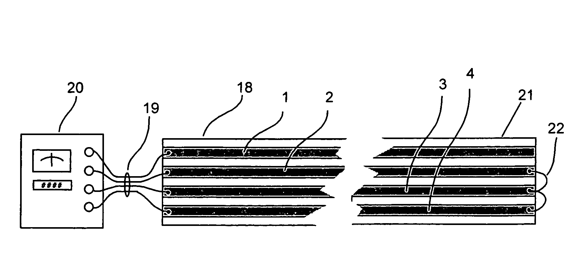
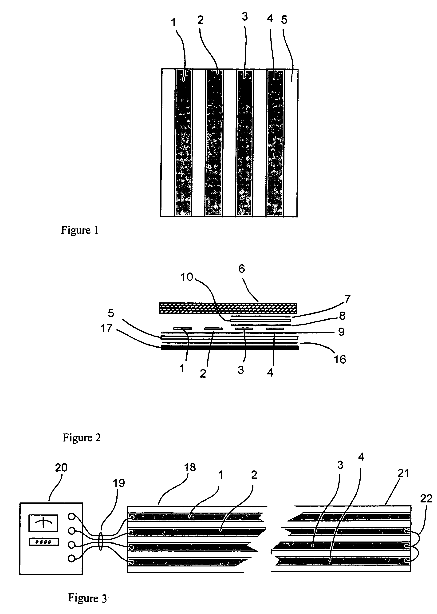
[0066]Referring to the accompanying drawings, and particularly FIGS. 1 and 2, there is illustrated a moisture detection tape. The tape is constructed by laminating two moisture detection copper strips 1 and 2 and two additional or loop-back copper strips 3 and 4 to a polyester substrate 6 using non-water soluble adhesive 9. An insulating layer of polyester 10 is laminated over the loop-back conductors using non-water soluble adhesive 8. A non-hygroscopic, non-woven, water pervious layer 6 is applied over the insulated loop-back conductors 3 and 4, detection conductors 1 and 2 and polyester substrate 5. A non-water soluble adhesive layer 16 that will adhere to common building materials such as wood, steel, concrete, etc. is applied to the underside of the polyester substrate 6. A 50.4 mm wide×0.1 mm thick peel off release layer 17 is applied over the underside adhesive layer 16.

[0067]The tape is constructed, in one example, by applying a non-water soluble adhesive 9 to a 50.4 mm wide...


PUM


Abstract

An elongated substantially flat four-conductor moisture detection and location sensor is described. The sensor includes four parallel conductors laminated to a dielectric substrate. Two of the conductors are protected by a water pervious dielectric layer and form the water-sensing element. Two other conductors are covered by a water impervious dielectric layer and are used to loop-back one or more of the water-sensing conductors. Precise location of a water leak location is determined by connecting the four conductors to a resistance bridge. The design allows for the connection of a four-conductor cable to extend the monitoring and detection point to a convenient location without loss of location accuracy.

Description

[0001]This application claims priority under 35 U.S.C. 119 from U.S. Provisional Application Ser. No. 60 / 712,833 filed Sep. 1, 2005.FIELD OF THE INVENTION[0002]The present invention relates to an apparatus and method for the detection and location of water penetration into residential and commercial roof structures.BACKGROUND OF THE INVENTION[0003]Water intrusion into roof structures is a major concern. Leaking roofs cost homeowners, commercial property owners and property insurers hundreds of millions of dollars every year. Even the smallest leaks can cause expensive problems. Structural damage to metal or plywood roof decking and rafters due to rot and rust has been commonplace for decades. Black mold or toxic mold that grows in the wet roof and wall areas is known to cause severe physical problems for occupants as well as severe fiscal problems for builders and insurance companies.[0004]Flat or low slope roofs are commonly used for commercial and multifamily building construction...

Claims


Application Information

Patent Timeline
Patent Type & Authority Patents(United States)
IPC IPC(8): G08B21/00
CPCE04D13/006G01M3/165G01M3/045
Inventor VOKEY, DAVID E.NASSAR, HANI
Owner DETEC SYST
Why Eureka
Try Eureka