Writing device for color electronic paper

Active Publication Date: 2007-11-06
E INK CORPORATION
View PDF6 Cites 95 Cited by
  • Summary
  • Abstract
  • Description
  • Claims
  • Application Information

AI Technical Summary

Benefits of technology

[0019]Since the color arrangement detector includes the photodetector and the above-mentioned members are made optically transparent, an arrangement state of the microcapsule is directly detected via the writing head. Thus, positional accuracy of color arrangement detection is improved.

Problems solved by technology

However, at the present point, there is no writing device which can perform rewriting with respect to the color electronic paper.
I

Method used


Image

  • Writing device for color electronic paper
  • Writing device for color electronic paper
  • Writing device for color electronic paper

Examples


first embodiment

[0059] Embodiment of the First Writing Device of the Present Invention

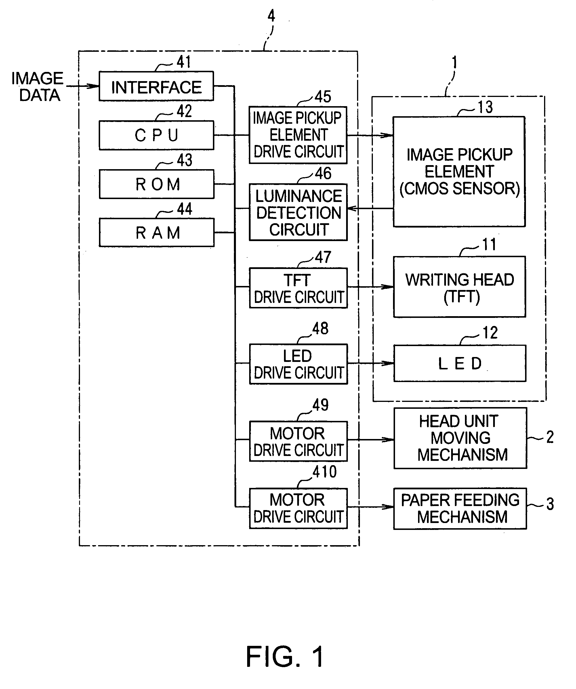
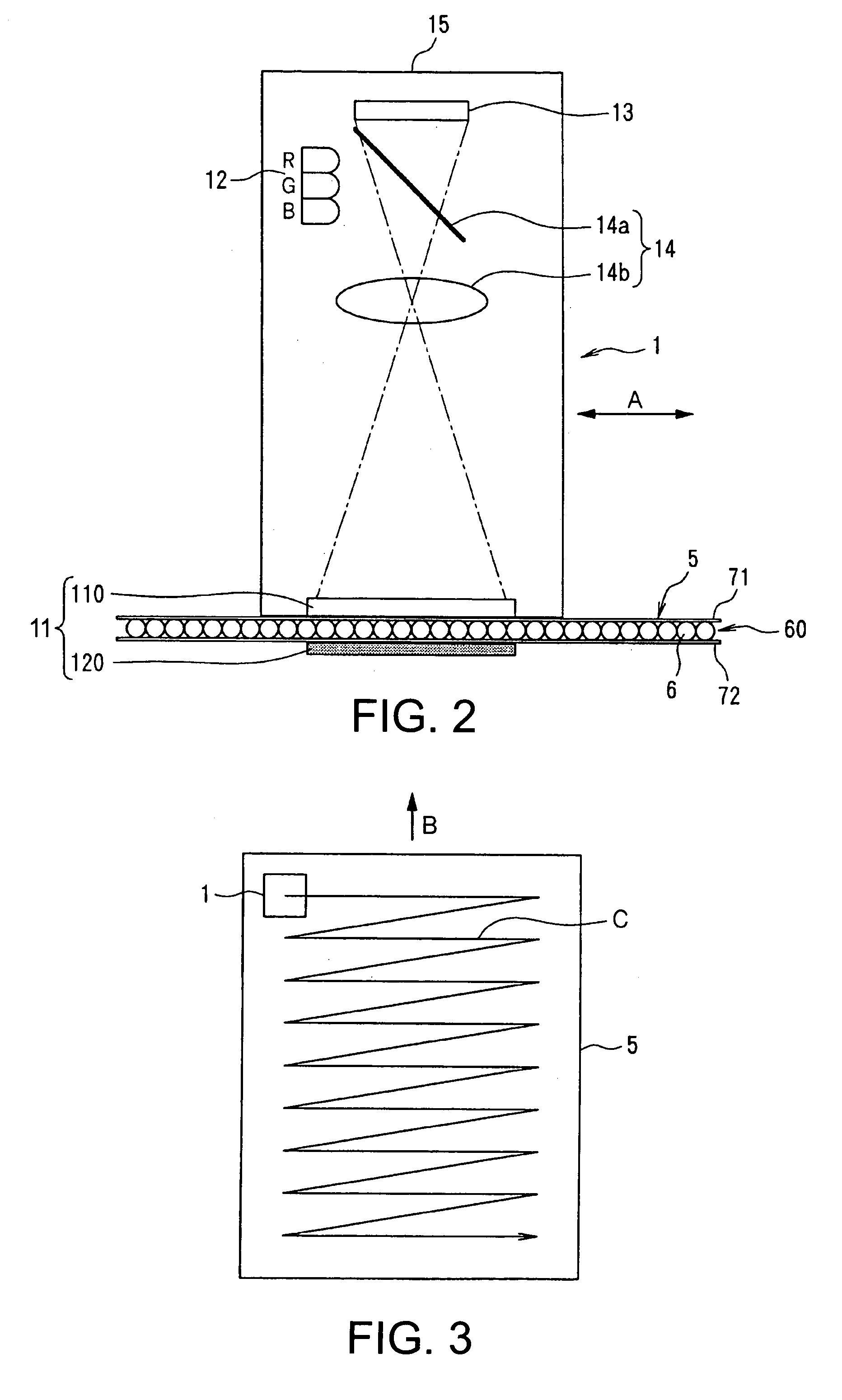
[0060]FIG. 1 is a block diagram showing a structure of a writing device of this embodiment. FIG. 2 is a schematic diagram showing a head unit. FIG. 3 is a plan view showing a moving locus of the writing device of this embodiment with respect to electronic paper.

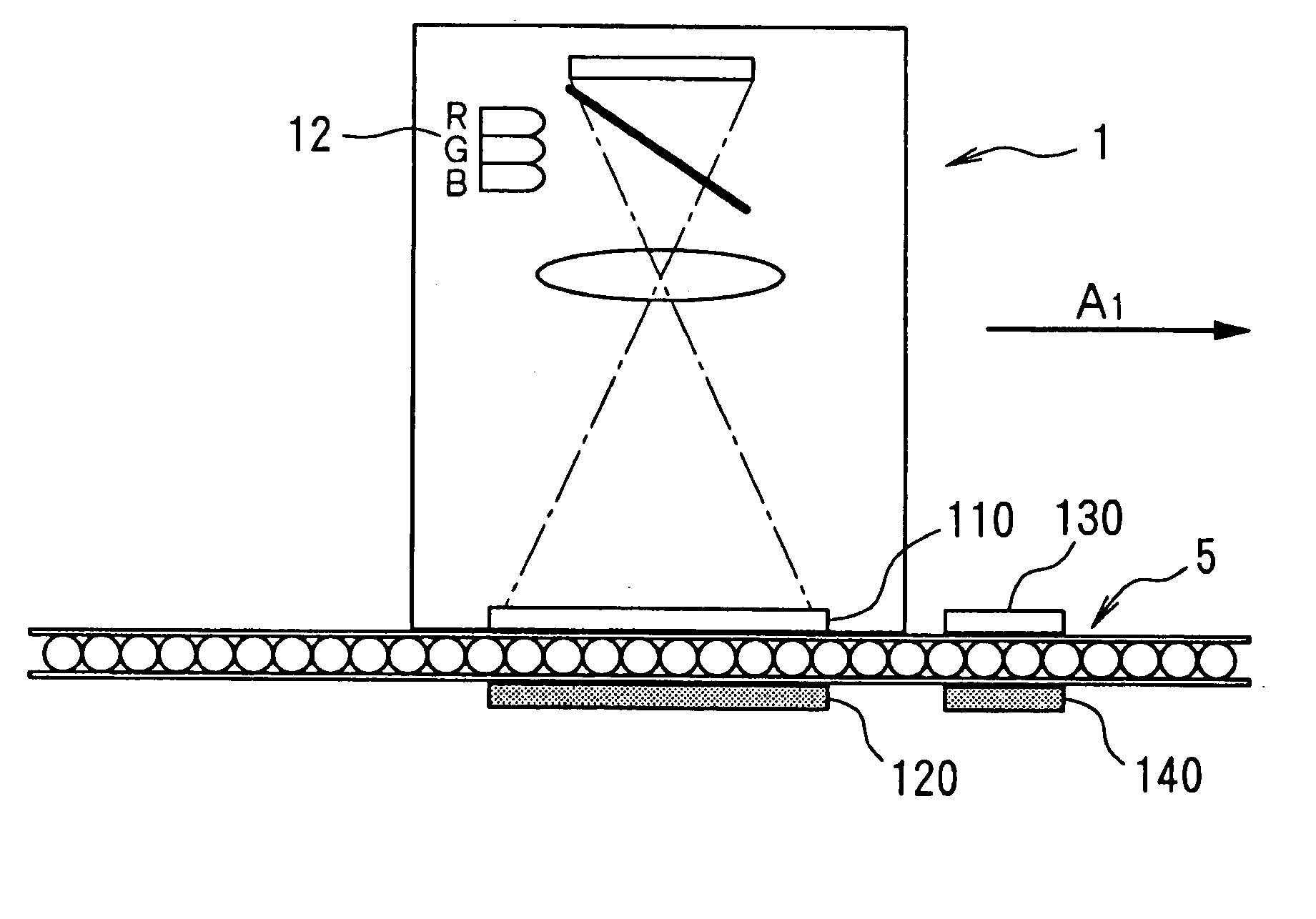
[0061]As shown in FIG. 1, the writing device of this embodiment includes a head unit 1, a head unit moving mechanism 2 which moves the head unit 1 in a direction A in FIG. 2, a paper feeding mechanism 3 which moves electronic paper 5 in a direction B in FIG. 3, and a controller 4. The head unit 1 is moved on a locus C shown in FIG. 3 relative to the electronic paper (color display medium) 5 by the head unit moving mechanism 2 and the paper feeding mechanism 3.

[0062]The head unit 1 includes a writing head 11, an LED 12 which emits light of three primary colors of R, G and B, an image sensing element 13 consisting of a CMOS sensor, and an optical system 14 wh...

second embodiment

[0091] Embodiment of the Second Writing Device of the Present Invention

[0092]FIG. 12 is a side view showing an embodiment of the writing device for color electronic paper (rewriting device for color electronic paper) of the present invention. A rewriting device for color electronic paper 21 shown in the figure is a device for drawing (displaying) a predetermined display pattern (display image) such as a character, a numeral, or a figure (picture) on color electronic paper 22 to be described later.

[0093]This rewriting device for color electronic paper 21 includes a line head 23 which erases a display pattern drawn on the color electronic paper 22 and draws a new display pattern, a paper feed roller 24 which conveys the color electronic paper 22, and a not-shown drive mechanism which rotates the paper feed roller 24. Note that a direction of arrow A in FIG. 12 is a conveying direction of the color electronic paper 22.

[0094]In addition, the color electronic paper 22 is a display medium...

third embodiment

[0175] Embodiment of the Second Writing Device of the Present Invention

[0176]A third embodiment is different from the second embodiment in that a display pattern of the color electronic paper 2, in which a plurality of stripe regions extend in the width direction, is rewritten.

[0177]More specifically, as shown in FIG. 25, a longitudinal direction of a relatively short line head 23 is arranged in a direction perpendicular to the axis of the paper feed roller 24, that is, perpendicular to the longitudinal direction of the stripe regions of the color electronic paper 22 (the erase head 25, the luminance sensor array 26, and the writing head 27 are arrange side by side so as to be along a direction perpendicular to the longitudinal direction of the strip regions), and a not-shown drive mechanism, which moves the line head 23 in the axis direction of the paper feed roller 24, is provided.

[0178]Further, in the rewriting process for color electronic paper executed in the control device 100...


PUM


Abstract

A writing device is provided for color electronic paper which is capable of performing full color display. The writing device includes a head unit, a head unit moving mechanism which moves the head unit in a first direction, a feeding mechanism which moves electronic paper, and a controller. The head unit includes a writing head, an LED which emits light of three primary colors, an image sensing element consisting of a CMOS sensor, and an optical system. The writing head includes an optically transparent head main portion provided with pixel electrodes, and a common electrode (counter electrode). In the controller, an arrangement of three types of microcapsules in a microcapsule layer is detected to perform electric field formation for each of the pixel electrodes based on a detection result.

Description

RELATED APPLICATIONS[0001]The present application claims priority to Japanese Patent Application No. 2003-088795 filed Mar. 27, 2003 and 2003-004357 filed Feb. 21, 2003.BACKGROUND OF THE INVENTION[0002]1. Field of the Invention[0003]The present invention relates to a writing device for color electronic paper which is capable of performing full color display.[0004]2. Related Art[0005]As a non-luminous type display device, there is known an electrophoretic display device which utilizes an electrophoresis phenomenon. The electrophoresis phenomenon is a phenomenon in which, when an electric field is applied to a dispersion liquid having particulates dispersed in a liquid phase dispersion medium, particles naturally charged by the dispersion (electrophoretic particles) migrate according to a Coulomb force.[0006]In a basic structure of the electrophoretic display device, one electrode is opposed to the other electrode at a predetermined interval, and the dispersion liquid (electrophoretic...

Claims


Application Information

Patent Timeline
IPC IPC(8): G09G3/00B01J13/02B41J2/385B65B1/00B67C3/00G02F1/167G03G15/32G09F9/00G09G3/02G09G3/34G09G5/00
CPCG03G15/326G09G3/001G03G15/04054G09G3/344G09G3/02
Inventor KODAMA, YOSHIYUKIHIRAMATSU, KAZUNORI
Owner E INK CORPORATION
Why Eureka
Try Eureka