System for searching device on network

a network and device technology, applied in the field of system for searching a device on the network, can solve the problem of inability to obtain the position information of the device for use, and achieve the effect of enhancing the efficiency of operation using various devices on the network

Inactive Publication Date: 2007-11-06
CANON KK
View PDF36 Cites 73 Cited by
  • Summary
  • Abstract
  • Description
  • Claims
  • Application Information

AI Technical Summary

Benefits of technology

[0011]Wherefore, the present invention has been developed to remove the above-described disadvantage, and an object thereof is to provide a system in which the position, attribute, and status of a desired device on network can visually easily be grasped, so that the efficiency of operation using various devices on network can be enhanced.

Problems solved by technology

However, in the synopsis list, the comprehensible position information of the device for use cannot be obtained.
Furthermore, another system has been demanded in which when an information processor on network is requested to execute printing or the like, the user is notified of information such as the place of the printer for the printing, the end state of one's requested printing, and the occurrence of errors such as jam and sheet shortage in the comprehensible manner.

Method used


Image

  • System for searching device on network
  • System for searching device on network
  • System for searching device on network

Examples


first embodiment

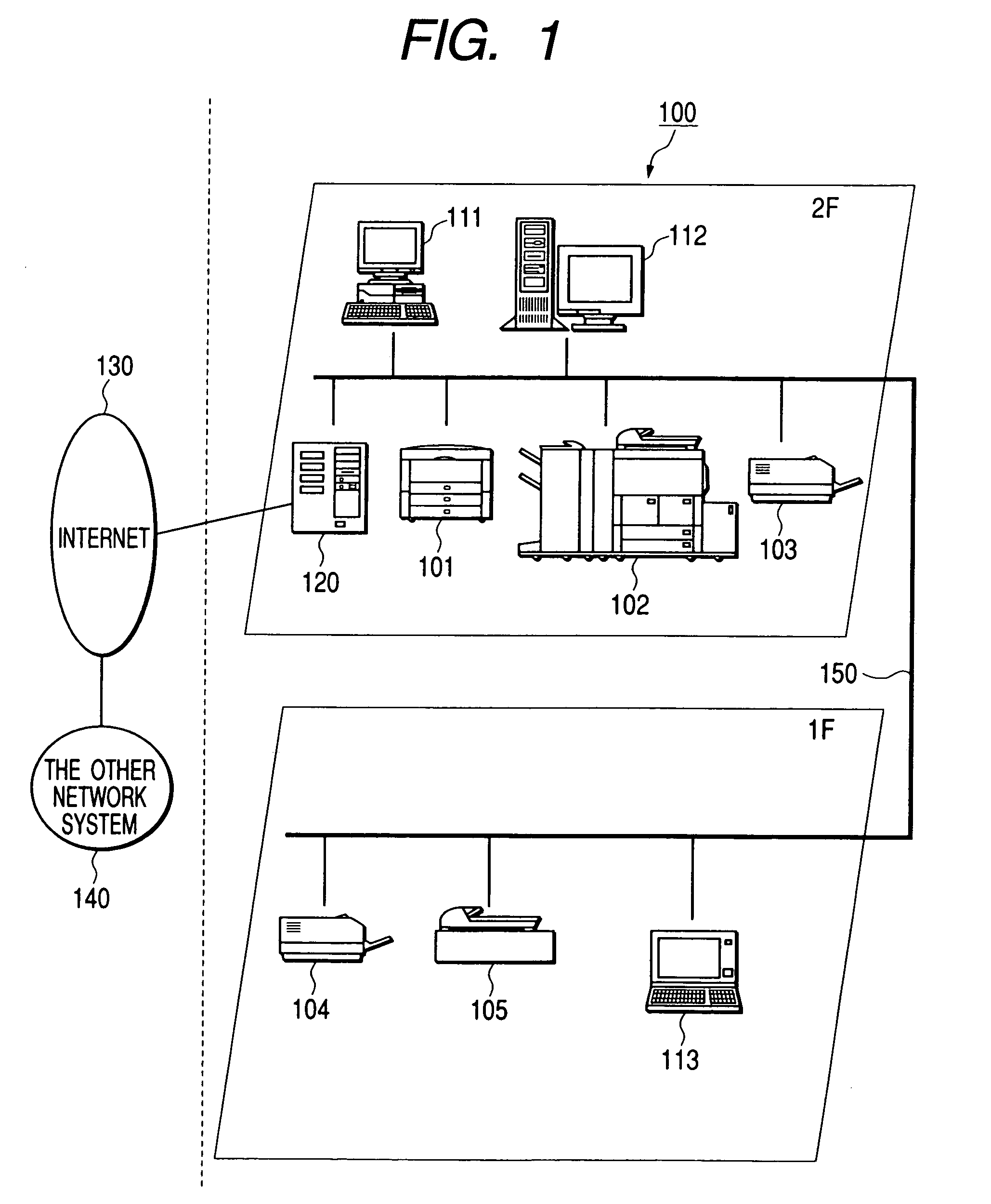
[0070]The present invention is applied, for example, to a network system 100 shown in FIG. 1.

[0071]The network system 100 is used on office floors including first and second floors, and as shown in FIG. 1, personal computers (PC) 111, 113 as information processors on a client side, a personal computer (PC) 112 as the information processor on a server side, and various devices 101 to 105 are connected via LAN 150 so that communication can be performed with one another.

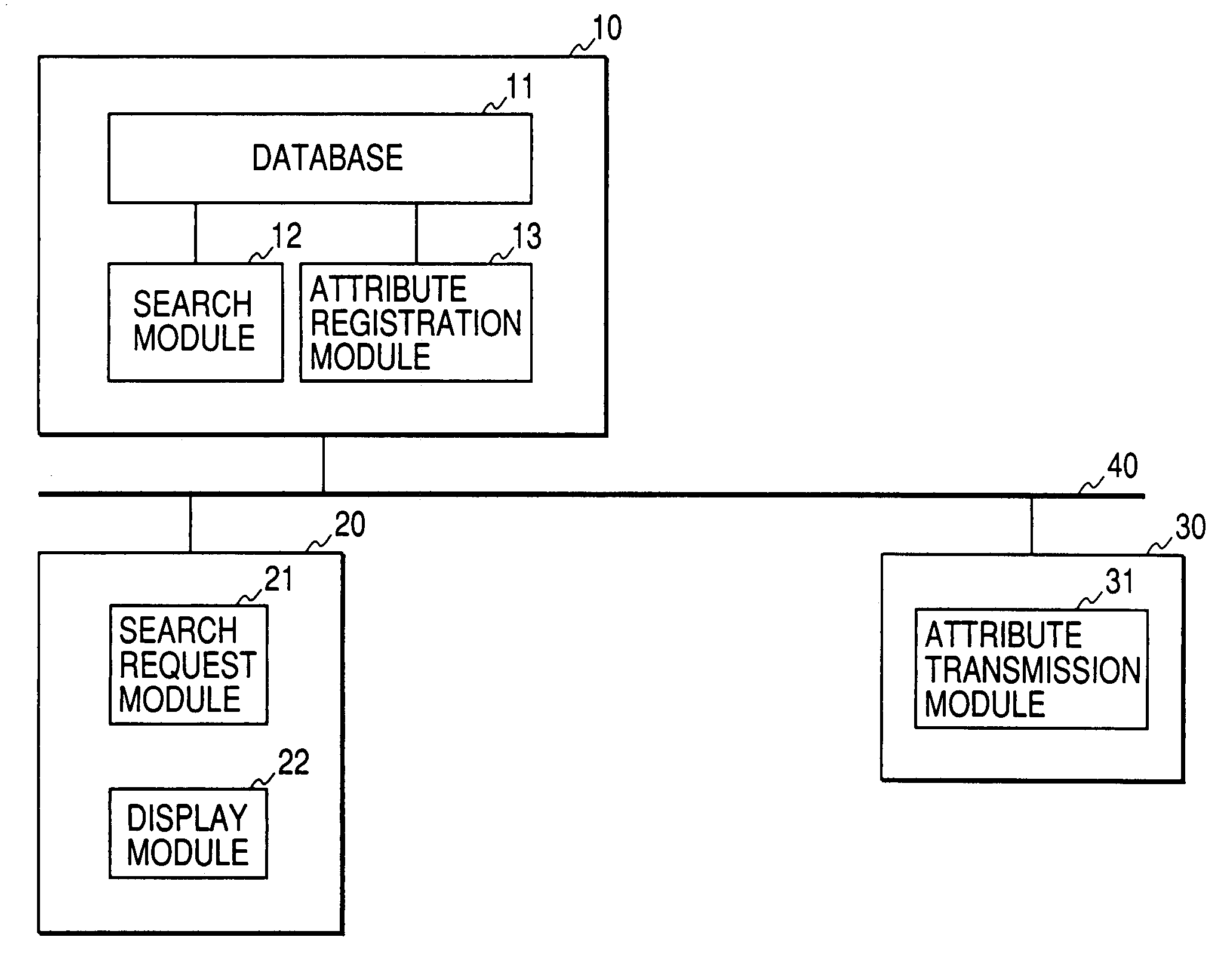
[0072]The PCs (client devices, hereinafter referred to simply as “client”) 111, 113 as the information processors on the client side can execute the program of a network device search client in the present embodiment, issue inquiry information on the device satisfying desired conditions to the PC (server device, hereinafter referred to simply as “server”) 112 as the server side information processor, and display the obtained search result.

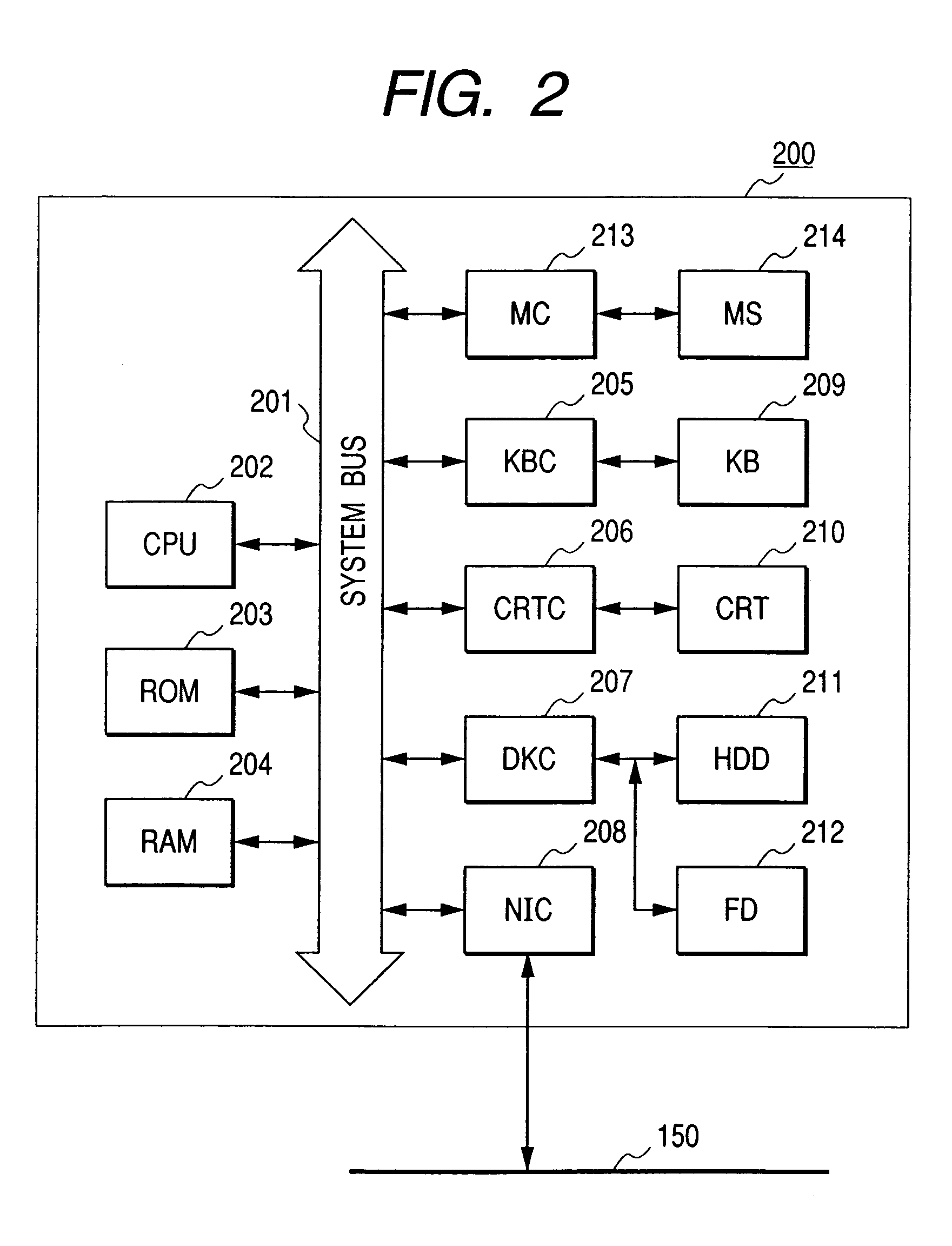
[0073]Moreover, in this example, the client 111 is constituted of a desktop PC, an...

second embodiment

[0272]Here, a form provided with a layout bit map for each hierarchy of the location information (position information) of the hierarchical structure as shown in FIG. 5 will be described.

[0273]First, in the above-described first embodiment, as shown in FIG. 19, as the layout bit map, there are five layout bit maps in total: respective block (BL) bit maps (MP1-2, MP1-2, MP2-1, MP2-2); and unknown bit map UMP.

[0274]On the other hand, in the second embodiment, each hierarchy is provided with the layout bit map. For this case, a display method on the client side will be described hereinafter.

[0275]Additionally, the display method of the present embodiment includes the above-described client display method.

[0276]FIG. 35 is a diagram showing a bit map list corresponding to each hierarchy to be searched (hereinafter referred to as “bit map correspondence list”).

[0277]A list shown below the bit map correspondence list corresponds to management information of MAP information shown in FIG. 19...

third embodiment

[0314]In the first and second embodiments, the layout bit map (MAP), held by the client 111, for representing the searched device position has been described, but in a third embodiment, a case where the layout bit map is held by the server 112 will be described.

[0315]Since the third embodiment is based on the first and second embodiments, mainly respects different from those of the above-described embodiments will be described in the third embodiment.

[0316]In the third embodiment, various layout bit maps, and the correspondence table of the hierarchical position information to the layout bit map shown in FIG. 19 are stored in the hard disk of the server 112.

[0317]FIG. 48 is a flowchart showing the general process of the server 112, and a processing of step S4808 is added to the flowchart (FIG. 27) of the first embodiment.

[0318]In step S4805, when the obtained event is MAP information obtaining request from the client, the process advances to step S4808 to execute a processing for re...


PUM


Abstract

There is disclosed a network system in which the position, attribute, and status of a desired device on a network can visually comprehensibly be grasped. A server manages location information indicating information on the device position in a hierarchical manner and attribute information from the device. Each device holds a plurality of status information (icon information) in accordance with various statuses of the device. A client holds map information corresponding to each class of the location information, and overlaps and outputs (display output) device status information obtained by communication by a polling system with the device detected by search in the server, and map information corresponding to the location information of the device.

Description

BACKGROUND OF THE INVENTION[0001]1. Field of the Invention[0002]The present invention relates to a system for searching a device on network, particularly to a device search system for displaying a searched device and position information.[0003]2. Related Background Art[0004]There has been heretofore provided, for example, a so-called directory service such as lightweight directory access protocol (LDAP) to efficiently find various resources such as a printer, a server, and a scanner (hereinafter also referred to as “device”) on network, and utilize the resources. The directory service functions as a telephone directory concerning so-called network, and is a service for managing and providing various information.[0005]Therefore, by utilizing the directory service and searching the device connected to the network, a list of network addresses of usable devices on the network can be obtained.[0006]Additionally, the definitions in the LDAP are described in RFC1777 issued by IETF.[0007]Ho...

Claims


Application Information

Patent Timeline
Patent Type & Authority Patents(United States)
IPC IPC(8): G06F15/16H04L12/24
CPCH04L41/044H04L41/12H04L41/22H04L41/08
Inventor MAKI, NOBUHIKOOCHIAI, MASATO
Owner CANON KK
Why Eureka
Try Eureka