Computing system and control method

a computer system and control method technology, applied in the field of job scheduling for a, can solve the problems of system lowering calculation efficiency and providing no advantages, system not knowing which part of raw data to use, and inability to effectively use a convergence calculation process

Inactive Publication Date: 2007-11-06
HITACHI LTD
View PDF7 Cites 86 Cited by
  • Summary
  • Abstract
  • Description
  • Claims
  • Application Information

AI Technical Summary

Benefits of technology

[0016]scheduling optimization by providing dynamic job scheduling even when multi-node calculations are to be conducted while the scheduled termination time is unknown; eliminating the necessity for centralized control over the system's job executions because each transmitting node autonomously performs job scheduling; and realizing job scheduling optimization in a scalable manner with regard to the number of nodes with no process conflicts because of the absence of the centralized control.

Problems solved by technology

If a single node performs multiple jobs at a time, that is, if the same node is involved in two or more multi-node calculations, the system lowers its calculation efficiency and provides no advantages.
At the beginning of the calculation process, however, the system does not know what part of the raw data should be used.
However, it cannot effectively be used for a convergence calculation process (which is repeatedly performed until the calculation results converge) or other process whose final processing volume will be determined according to intermediate calculation results.
However, this method is not suitable for scalable job scheduling optimization applicable to large-scale multi-node calculations involving hundreds of nodes because it may incur table access conflicts.

Method used


Image

  • Computing system and control method
  • Computing system and control method
  • Computing system and control method

Examples


Embodiment Construction

[0038]It is to be understood that the figures and descriptions of the present invention have been simplified to illustrate elements that are relevant for a clear understanding of the present invention, while eliminating, for purposes of clarity, other elements that may be well known. Those of ordinary skill in the art will recognize that other elements are desirable and / or required in order to implement the present invention. However, because such elements are well known in the art, and because they do not facilitate a better understanding of the present invention, a discussion of such elements is not provided herein. The detailed description of the present invention and the preferred embodiment(s) thereof is set forth in detail below with reference to the attached drawings.

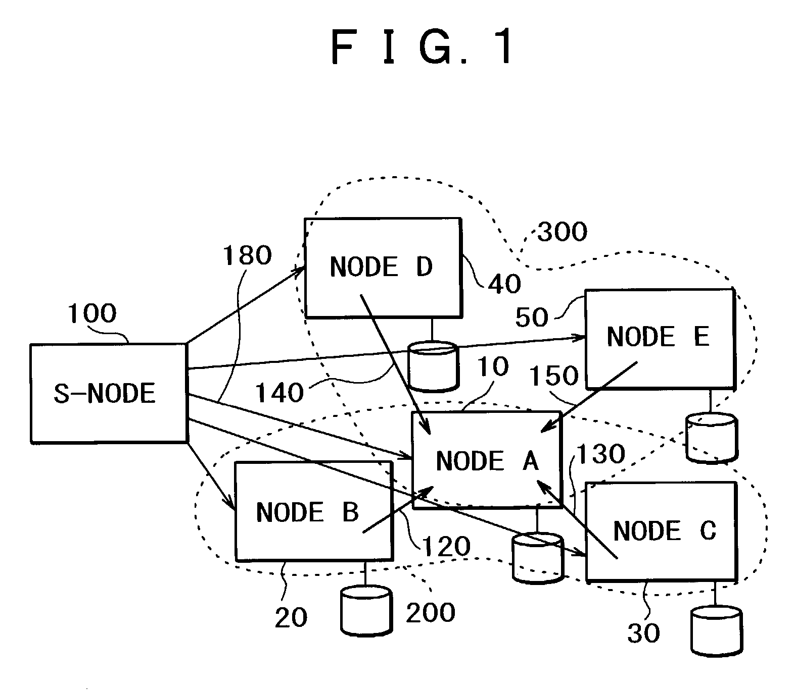
[0039]FIG. 1 is a conceptual diagram of a computing system of the first preferred embodiment of the present invention.

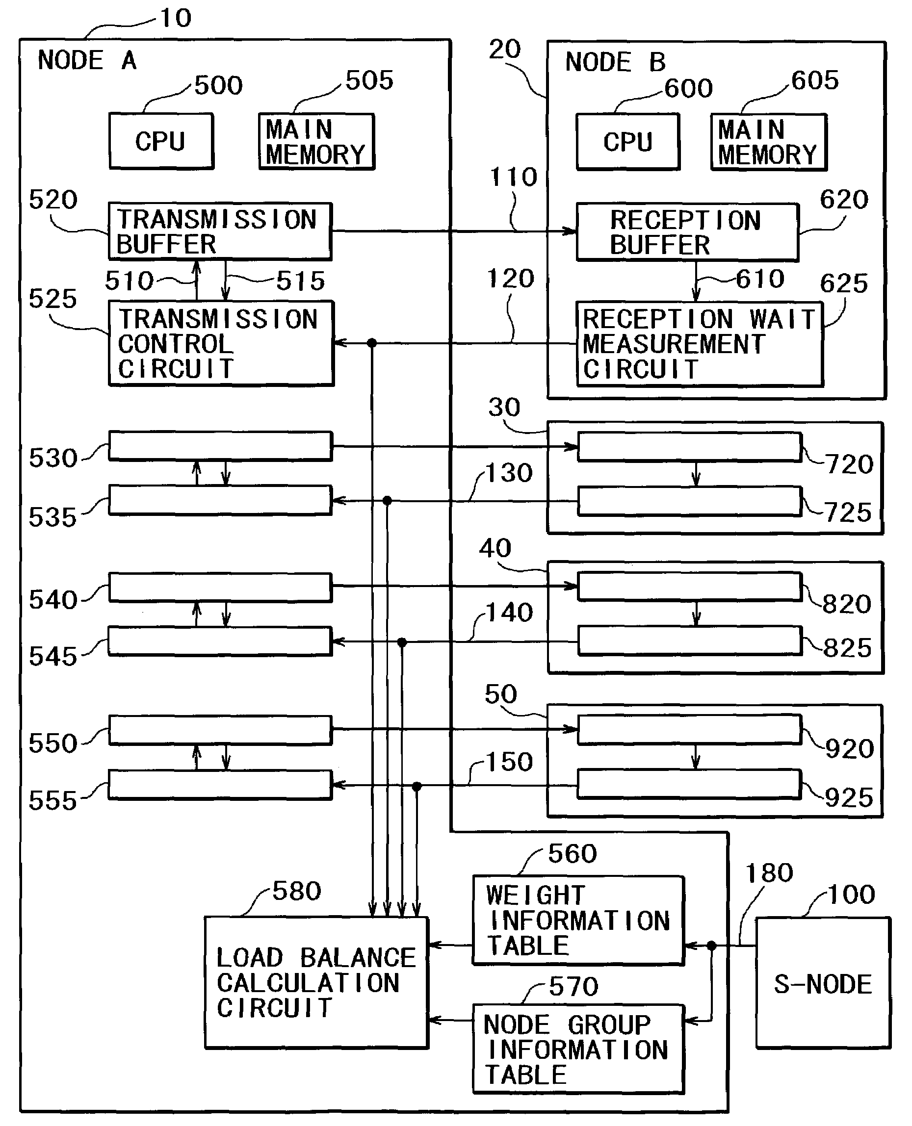
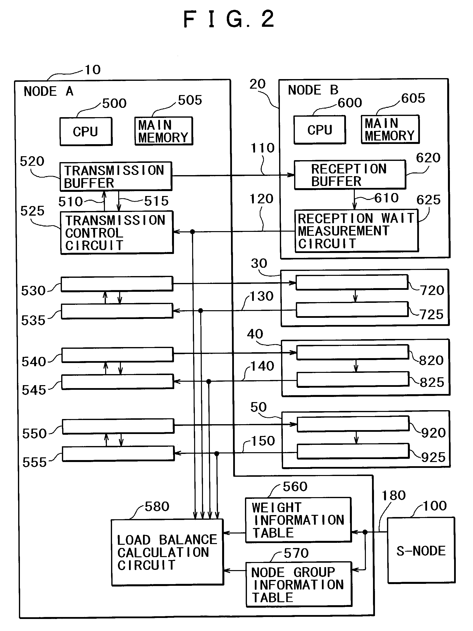
[0040]Calculations are performed by node A 10, node B 20, node C 30, node D 40, and node E 50 ...


PUM


Abstract

A parallel or grid computing system that having a plurality of nodes and achieves job scheduling for the nodes with a view toward system efficiency optimization. The parallel or grid computing system has a plurality of nodes for transmitting and receiving data and a communication path for exchanging data among the nodes, which are either a transmitting node for transmitting data or a receiving node for processing a job dependent on transmitted data, and further has a time measuring means for measuring the time interval between the instant at which data is called for by a job and the instant at which the data is transmitted from a transmitting node to a receiving node, a time counting means for adding up the measured wait time data about each job, and a job scheduling means for determining the priority of jobs in accordance with the counted wait time and for scheduling jobs.

Description

BACKGROUND OF THE INVENTION[0001]1. Field of the Invention[0002]The present invention relates to job scheduling for a parallel or grid computing system comprising a plurality of nodes and, more particularly, to a method for determining the priority of jobs so as to increase the overall system efficiency and a communication scheme for implementing such a priority determination method.[0003]2. Description of the Related Art[0004]A system in which nodes having one or more CPUs and a main memory are interconnected via a network to exchange jobs and data or operated in coordination with each other to perform calculations on a large scale is called a parallel or grid computing system. The parallel or grid computing system is an essential configuration for establishing a large-scale system where more than 1000 CPUs are used. The difference between the grid computing system and parallel computing system arises from the system's physical expanse and network performance and specifications. Ho...

Claims


Application Information

Patent Timeline
Patent Type & Authority Patents(United States)
IPC IPC(8): G06F15/173G06F15/16G06F9/46G06F9/48G06F9/50G06F15/177
CPCG06F9/4843
Inventor SUKEGAWA, NAONOBU
Owner HITACHI LTD
Why Eureka
Try Eureka