Method of operating a gas turbine group

a gas turbine and group technology, applied in the direction of engines, machines/engines, mechanical apparatus, etc., can solve the problems of increasing the attainable maximum power of the gas turbine group, the internal cooling of the compressor, and the maximum power, so as to reduce the cooling effect, reduce the effect of fuel burnout and stable operation

Inactive Publication Date: 2007-11-13
ANSALDO ENERGIA IP UK LTD +1
View PDF12 Cites 36 Cited by
  • Summary
  • Abstract
  • Description
  • Claims
  • Application Information

AI Technical Summary

Benefits of technology

[0014]To cool the working fluid, in a preferred method variant of the method according to the invention, a liquid, in particular water, is injected upstream of the compressor inlet. Due to evaporation, this effects a cooling of the mass flow of the working fluid before compression. If liquid penetrates into the compressor—perhaps because the injection location is very close to the compressor inlet or because the injection quantity is so large that the working fluid is supersaturated at the compressor inlet—the penetrating liquid continues to effect cooling during the compression. The liquid quantity introduced is, in this case, a measure of the cooling effect.
[0019]It is particularly advantageous to define, around the required value, a dead band within which no interventions are undertaken on the cooling effect. One process would, for example, be conceivable in which the relative power required value is 90%, with a dead band of ±5%. A control intervention then only takes place if the actual relative power falls to under 85% or climbs to over 95%. This fundamentally ensures a power reserve, which can be rapidly mobilized, of at least 5% of the full-load power. The wide dead band ensures that the control system does not react in an oversensitive manner, and that the number of control interventions remains limited to a minimum, which is certainly in the interest of a stable operation. The operational process can, of course, also provide for the relative power to be generally kept within a certain target range. If the operating concept of the gas turbine group provides for the turbine inlet temperature or the turbine inlet temperatures to be kept to a certain value, for example the permissible maximum value, by control of an adjustable inlet guide vane row—and, if appropriate, also further adjustable compressor guide vane rows—it is possible to employ, as a further criterion for a control intervention, that the inlet guide vane row should be located in the fully closed position and the turbine inlet temperature should fall to below the maximum permissible value. With this assumption, it is sensible to undertake a control intervention even if the power is still located within the dead band, and to reduce the cooling effect. In this way, the fuel burn-out can be kept high and the emission of carbon monoxide and unburnt hydrocarbons can be kept low.
[0021]Summarizing, it should be again stated that the core of the invention consists in operating a gas turbine group with variable cooling of the induced or partially compressed working fluid; preferably by the injection of a liquid, in particular water, before the compressor, in the compressor, or between two compressor steps, and, in the process, to set the cooling effect in such a way that although the operating condition, for a respective actual power output of the gas turbine group is close to the full-load operating point of the gas turbine group in each case, which for example ensures favorable emission values and a good efficiency, it is always also set below the full-load power, by which means a power reserve is made available which can be more rapidly mobilized than it could if it had to be first made available by means of the variable cooling. In this case, control of different operating parameters of the gas turbine group, which characterize the operating point of the gas turbine group relative to the full-load operating point, can be used as the command parameter for the control system. As suitable command parameters should be particularly mentioned the relative power, which is defined in each case as the current useful power referred to the current full-load useful power which depends on the cooling effect, also a power reserve from the useful power to the respective full-load power, a turbine entry temperature, or a setting of an adjustable compressor guide vane row, in particular an adjustable inlet guide vane row. The cooling effect is then controlled in each case in such a way that the command parameter is set to a required value or within a target range. In the case of control to a target value, a dead band is advantageously defined around the required value, within which dead band the control unit is deactivated in order to prevent an oversensitive intervention of the control unit in the case of the smallest deviations.

Problems solved by technology

The droplets evaporate within the compressor, during the compression process, and this leads to intensive internal cooling of the compressor.
Overall, this results in an increase in the attainable maximum power of the gas turbine group, which maximum power is, of course, mainly limited by the mass flow of the working fluid and the permissible turbine inlet temperature.
Likewise, the transit times of the components in the regulation and control mechanisms frequently used in gas turbine groups delay the detection of the temperature changes effected by the water injection and also, therefore, their effect on the fuel supply.
In consequence, it is found that the water injection only becomes effective with a time lag.
Similarly, it is impossible to realize an arbitrarily rapid switching on of the injected water quantity and an arbitrarily rapid increase of it.
In addition, it is found that the dead periods and delay times, as described above, of a control line reduce the stability of a control circuit in such a way that the possible reaction speed is greatly reduced.
Summarizing, therefore, the use of measures for cooling the working fluid during the compression and, in particular, the injection of water before the compressor, cannot be used to an unlimited extent for rapid increases in power.

Method used


Image

  • Method of operating a gas turbine group
  • Method of operating a gas turbine group
  • Method of operating a gas turbine group

Examples


Embodiment Construction

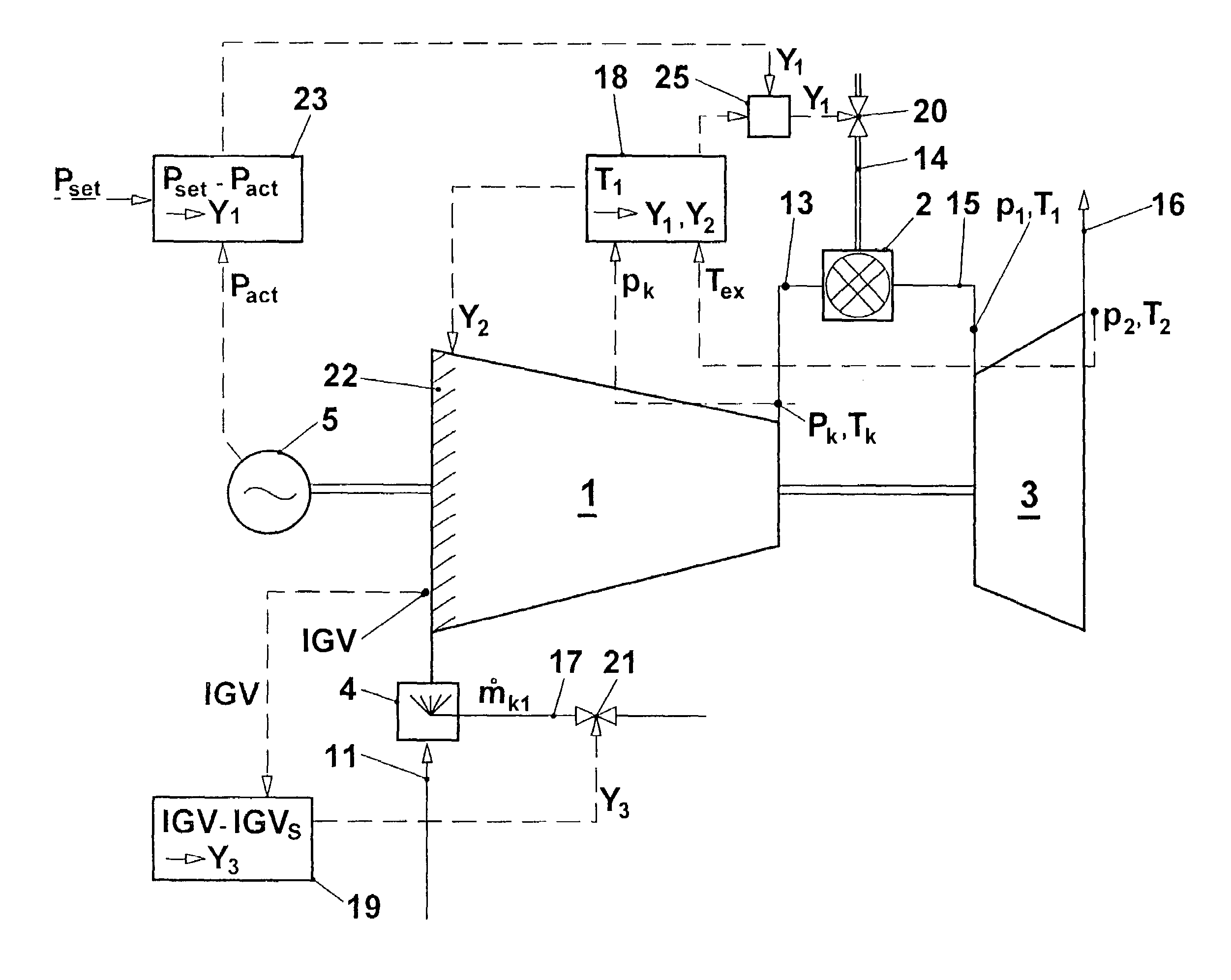
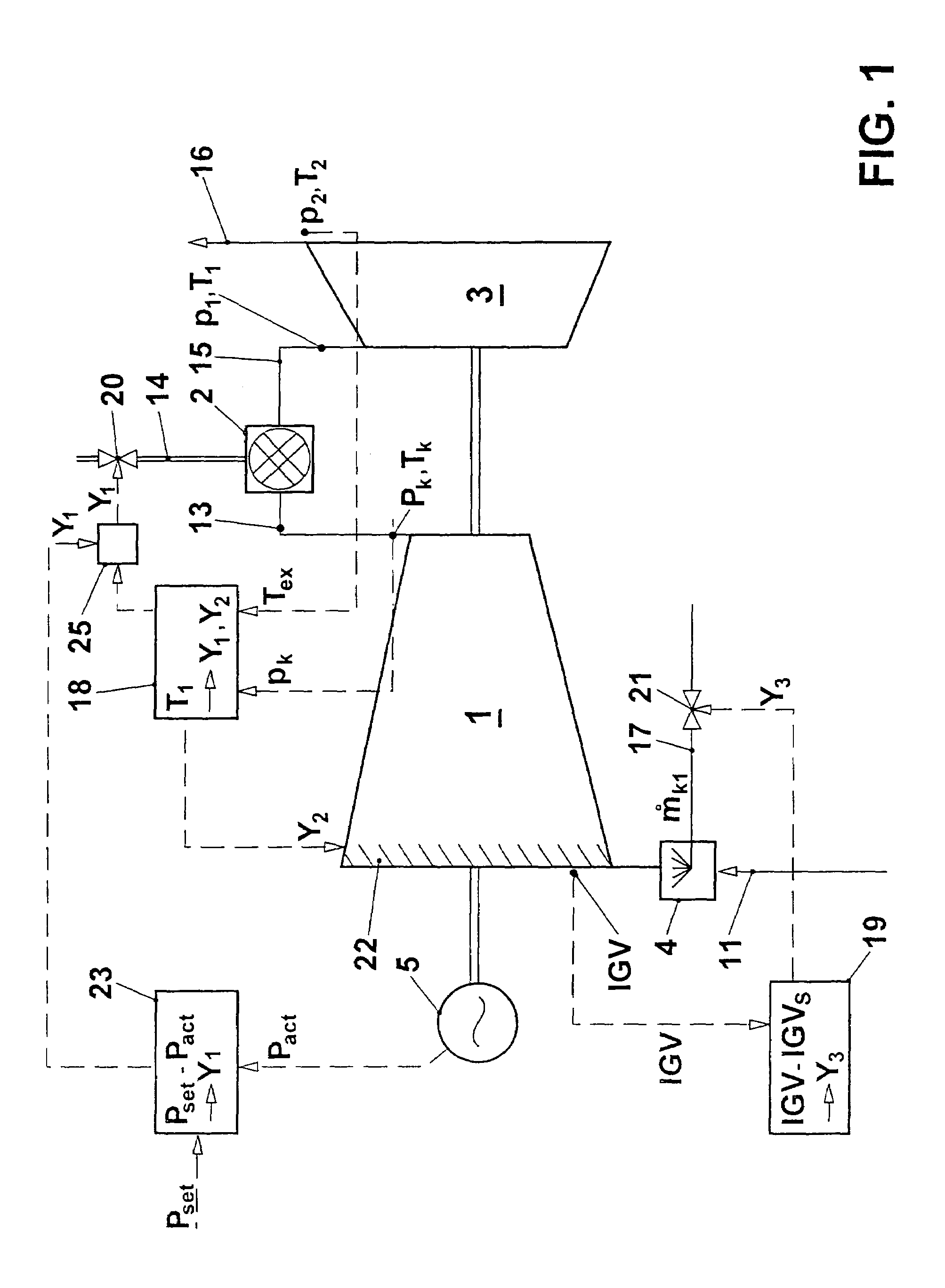
[0028]In the gas turbine group represented in FIG. 1, a flow of working fluid, an induced air flow 11 in the present case, is compressed in a compressor 1 to a pressure pk and, in the process, is heated to the temperature Tk. The compressed air 13 flows into the combustion chamber 2. A fuel quantity 14, which is metered by a fuel quantity setting unit, is mixed with the compressed air 13 and is there burnt in the air. The unexpanded hot combustion gas 15 flows with the pressure p1 and the turbine entry temperature T1 into the turbine 3. The pressure p1 corresponds, essentially, to the compressor exit pressure pk, reduced by the combustion chamber pressure loss. The unexpanded combustion gas 15 is expanded in the turbine 3 to a pressure pex. This corresponds, essentially, to the ambient pressure. During the expansion, work is performed in the turbine. The exhaust gas 16 flows away with a temperature Tex and can, in a manner known per se, be used in a waste-heat steam generator, for e...


PUM


Abstract

In a method for operating a gas turbine centre in the vicinity of the group nominal full-load conditions, the cooling of the working fluid before and / or during the compression is set in such a way that the respectively attainable full-load power is above the current power. Rapid power demands can therefore be rapidly satisfied by an increase in the turbine inlet temperature or by opening an adjustable inlet guide vane row, whereas the control of the cooling effect, which has a tendency to be more sluggish, is employed to adjust the full-load operating point.

Description

CROSS-REFERENCE TO RELATED APPLICATIONS[0001]This application is a continuation of the U.S. National Stage designation of co-pending International Patent Application PCT / EP2004 / 050086 filed Feb. 5, 2004, which claims priority to Swiss patent application no. 2003 0207 / 03 filed Feb. 11, 2003, and the entire contents of these applications are expressly incorporated herein by reference thereto.FIELD OF THE INVENTION[0002]The present invention relates to a method of operating a gas turbine group.BACKGROUND OF THE INVENTION[0003]From U.S. Pat. No. 5,353,585, a method has become known in which atomized water is introduced into the induced air flow before the compressor of a gas turbine group. Due to evaporation cooling, the density of the induced air is increased and, with it, the mass flow of the working fluid and the maximum attainable power of the gas turbine group.[0004]In U.S. Pat. No. 6,216,443, injecting water is proposed in such a way that liquid droplets enter the compressor. The ...

Claims


Application Information

Patent Timeline
Patent Type & Authority Patents(United States)
IPC IPC(8): F02C3/30F02C9/00F02C7/057F02C7/143F02C9/28F02C9/54
CPCF02C7/057F02C7/1435F02C9/28F02C9/54F05D2270/053F05D2270/303F05D2270/301F05D2270/091
Inventor HOFFMANN, JURGENMCKAY, TOM ALEXANDER ODINKURZ, NIKOLAUS HERBERTSPITZMULLER, TOBIAS
Owner ANSALDO ENERGIA IP UK LTD
Why Eureka
Try Eureka