
Walk aerator with ground following coring head

a walk aerator and coring head technology, applied in the field of aerators, can solve the problems of aerators that aerators can not be buried, and the hole is left behind from the hole prematurely chopping the soil core, so as to achieve the effect of constant depth of the hol

Inactive Publication Date: 2007-11-13
TORO CO THE
View PDF1 Cites 18 Cited by
  • Summary
  • Abstract
  • Description
  • Claims
  • Application Information

AI Technical Summary

Benefits of technology

The invention is a device called a walk aerator that can be used to punch holes in the ground. It has a frame, a handle, and a coring head that can be adjusted vertically on the frame. The device is designed to automatically adjust the depth of the holes based on changes in the ground contour, so that the holes are always at the same depth regardless of the type of ground they are walking on. This makes it easier to create consistent holes in the ground.

Problems solved by technology

When doing so, the wheels can compact previously formed holes or prematurely crush soil cores left from such holes.
This is a disadvantage.
Another difficulty with prior art aerators presents itself when such aerators operate over uneven terrain.
Some coring holes will be too shallow and other coring holes too deep.
The crankshafts used in prior art aerators are typically expensive and must be precisely cast or machined.
This may take too much weight off the other end of the frame, limiting steering and / or traction from the ground engaging wheels carried on the other end of the frame.

Method used


Image

  • Walk aerator with ground following coring head
  • Walk aerator with ground following coring head
  • Walk aerator with ground following coring head

Examples


Embodiment Construction

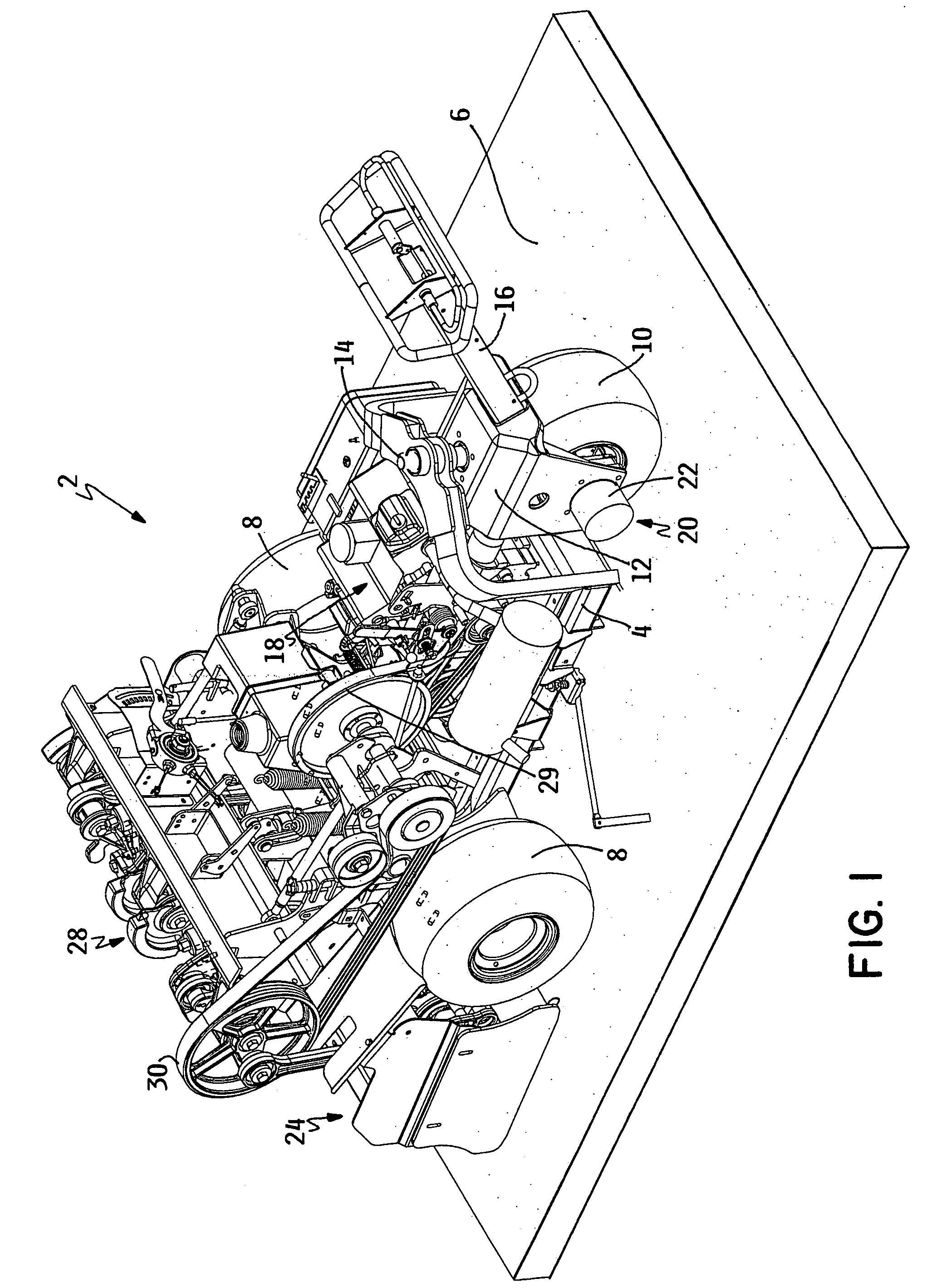
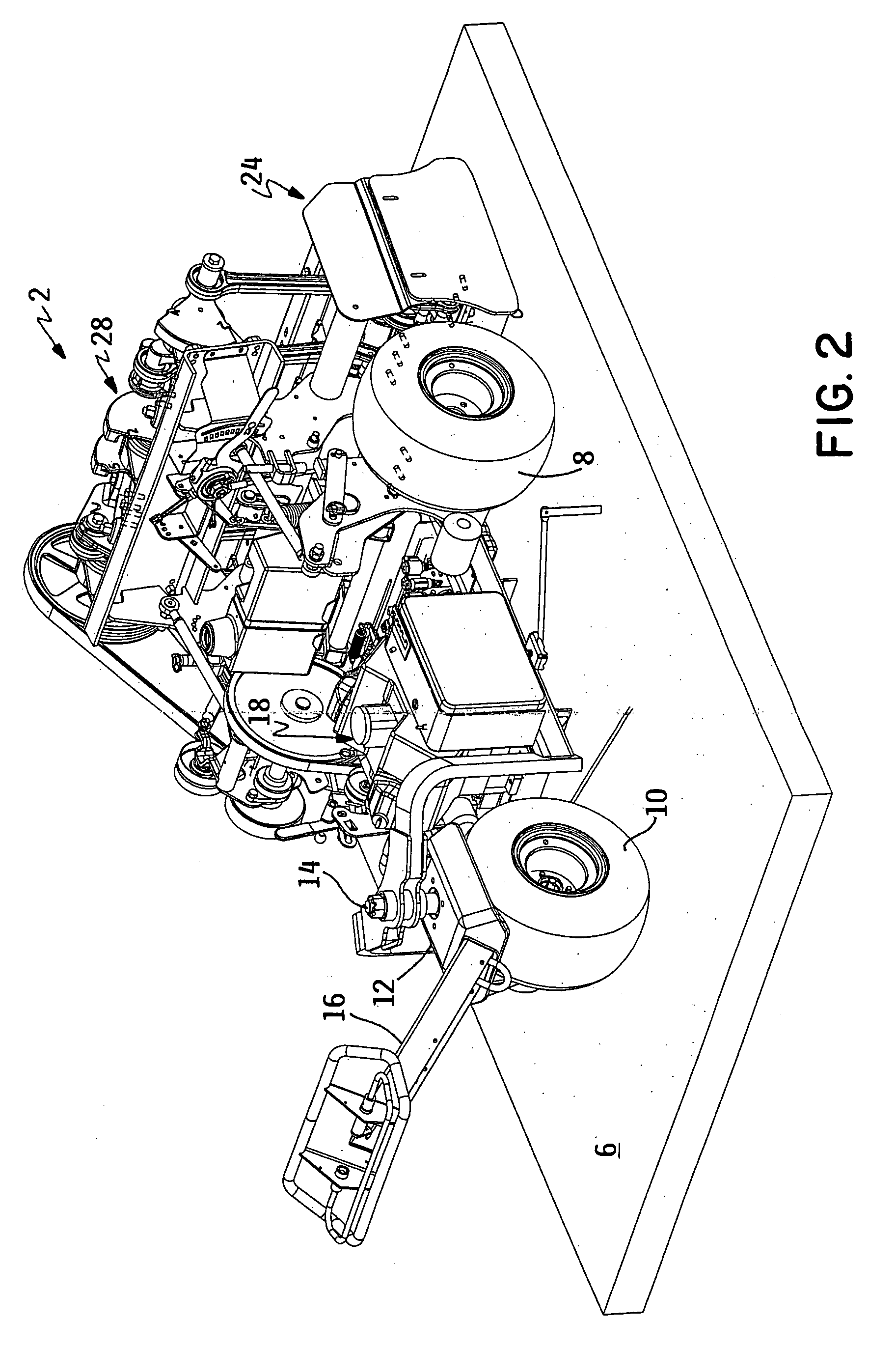
[0030]Referring first to FIGS. 1-6, the aerator of this invention is generally illustrated as 2. Aerator 2 comprises a frame 4 supported for movement over the ground 6 by a pair of rear wheels 8 and a front wheel 10 in a tricycle configuration. Front wheel 10 is carried in a pivotal yoke 12 that rotates about a substantially vertical pivot axis 14. An upwardly and forwardly extending handle assembly 16 is coupled to pivotal yoke 12 that carries front wheel 10. Thus, an operator who walks ahead of frame 4 can steer aerator 2 by using handle assembly 16 to steer or pivot front wheel 10 about substantially vertical pivot axis 14.

[0031]Frame 4 carries a prime mover 18 in the form of an internal combustion engine, though other prime movers such as an electric motor could also be used. Prime mover 18 provides power to a traction drive 20 for propelling frame 4 over ground 6 by driving one or more of wheels 8 or 10. Traction drive 20 could comprise a mechanical drive having mechanical tran...


PUM


Abstract

A walk aerator comprises a frame supported by a plurality of ground engaging wheels, the frame carrying a coring head having a plurality of side-by-side tine assemblies. The wheels define a wheelbase which is substantially equal to or less than the width of a coring swath and the wheels are located in advance of the coring head to keep the wheels from passing over the holes or soil cores left in any preceding coring swathes formed by the aerator. The vertical position of the coring head is adjustable up and down as the ground contour changes to keep hole depth substantially constant. The tine assemblies are reciprocated by a single crankshaft driven by a single pulley, the crankshaft being assembled from multiple crank arms that are splined and bolted together. Sealed bearings connect drive arms that drive the tine assemblies to the crankshaft. The crankshaft can be disassembled to allow the sealed drive arm bearings to be replaced. Integral core deflectors are used on the drive arms. A connecting link extending across each drive arm is used to connect each drive arm to the coring head to decrease the coring head depth.

Description

CROSS REFERENCE TO RELATED APPLICATIONS[0001]This application is a division of application Ser. No. 10 / 706,607, filed Nov. 12, 2003 now U.S. Pat. No. 7,096,969, which claims the benefit of one or more previously filed copending provisional applications identified as follows: Application Ser. No. 60 / 425,375 filed Nov. 12, 2002.TECHNICAL FIELD[0002]This invention relates to an aerator for punching coring holes in the ground for aerating the turf or soil. More particularly, this invention relates to an aerator for use on relatively hilly and undulating terrain, such as that found on golf courses of the like, that is guided and operated by a walking operator.BACKGROUND OF THE INVENTION[0003]Walk aerators are well known for aerating an area of the ground by punching holes in the ground. Such aerators are guided by a walking operator who holds a handle assembly. Such aerators include a coring head that is carried on the aerator frame. The coring head includes a plurality of vertically rec...

Claims


Application Information

Patent Timeline
Patent Type & Authority Patents(United States)
IPC IPC(8): A01B45/02
CPCA01B45/023
Inventor PETERSEN, WALTER J.POMERENING, GERALD J.
Owner TORO CO THE
Learn More