
Electrophoretic separating device and method for using the device

a technology of electrophoretic separation and separating channel, which is applied in the direction of fluid pressure measurement, liquid/fluent solid measurement, peptide measurement, etc., can solve the problems of inability to arrange the dense packing of a multitude of separating channels onto one carrier substrate, cumbersome and tedious techniques, and inability to achieve continuous electrophoretic media in capillary electrophoresis, etc., to achieve fast and convenient electrophoretic separation of complex samples, high-performance and cost-

Inactive Publication Date: 2007-11-13
INST FOR BIOMEDICAL +1
View PDF9 Cites 7 Cited by
  • Summary
  • Abstract
  • Description
  • Claims
  • Application Information

AI Technical Summary

Benefits of technology

[0019]It is an object of the invention to provide a device and a method for fast and convenient, high-performance and cost-effective electrophoretic separation of complex samples. Good separation performance shall be implemented by the realization of sample concentration in an electrophoretic channel filled with a homogeneous medium resulting in narrow electrophoretic bandwidths.
[0020]It is a further object of the invention to miniaturize the separating device onto chip-based systems. The use of the device as well the handling of the electrophoretic separating method shall be easy and secured.
[0023]The problem of low electrophoretic separation performance of concentration-limited samples, especially in miniaturized CE, is overcome by the invention which can generate a discontinuous electric field along the separation channel which is filled with a homogeneous medium. The electrophoresis channel consists of several, at least two, sections (n≧2) in series with n−1 joints between n sections. To establish different electric fields in the consecutive sections, electrodes are connected at the joints. To avoid disturbances in the separation channel by electrochemical reaction products and gas-bubble formation, these electrode connections are realized by inserting a solid ion conductive material as a membrane between the electrophoresis channel and a vial apart the channel. These vials are provided with electrodes and filled with appropriate electrolyte. By connecting the vial-electrodes to a direct current voltage supply, the buffer ions in the electrolyte can be interchanged through the ion-conductive membrane between the vials and the separation channel. By selecting appropriate membrane, the passing of sample ions to be analyzed can be prohibited by selectivity of the membrane. Thus a purely ionic connection to the joints of the separation channel is realized.

Problems solved by technology

The majority of practical samples, for example in medicine or environmental and bioprocess monitoring, are concentration-limited, i.e. samples where the amount of the component to be analyzed is limited by its concentration in the sample and not by the available sample volume.
Discontinuous electrophoretic media in capillary electrophoresis can only be realized by cumbersome and tedious techniques, and only once for each sample.
Due to the fact that the separating channel is square no dense packing of a multitude of separating channels isn t possible to arrange onto one carrier substrate.

Method used


Image

  • Electrophoretic separating device and method for using the device
  • Electrophoretic separating device and method for using the device
  • Electrophoretic separating device and method for using the device

Examples


Embodiment Construction

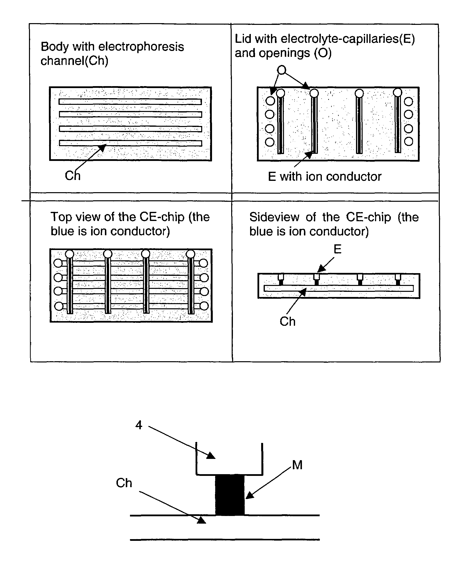
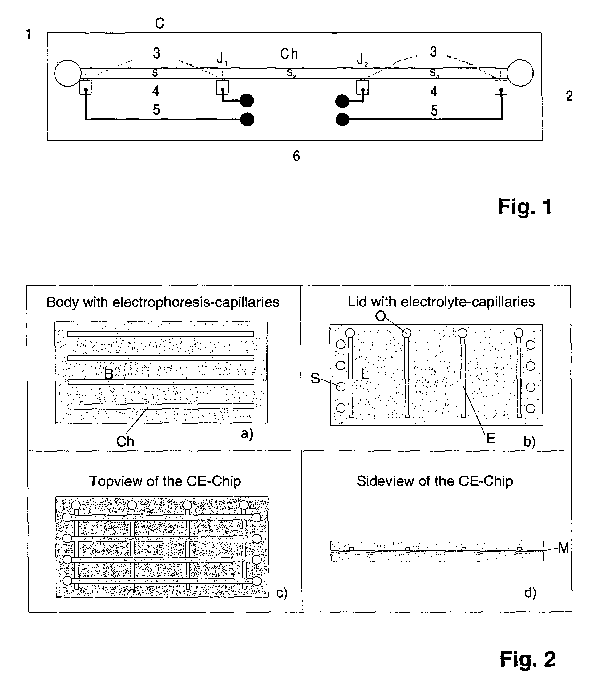
[0033]FIG. 1 shows an electrophoretic separating device C having the electrophoresis channel Ch consists of several sections Sn (e.g. n=3 or 4) in series with n−1 joints Jn−i between n sections. The channel is made of one piece advantageously is provided with in- and outlet 1, 2 openings at the ends. A sample to be separated is injected via a feed opening (e.g. identical with the inlet (1)) into an electrophoretic carrier medium. In the channel sections different electric fields are generated by electrodes in the region of the in- and outlet openings and at the joints between the sections.

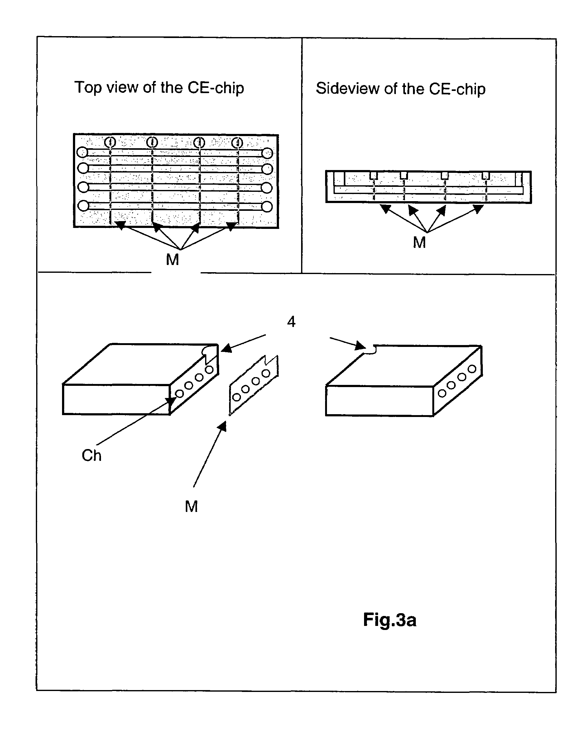
[0034]To prevent electrochemical reactions and gas-bubble formation in the separation channel Ch, the electric fields in the channel are established using ion-conductive materials 3, constructed for example as a membrane, between the channel Ch and a reservoir 4 apart the channel, provided with an electrode 5, which can be connected by interconnections 6 to direct voltage sources, and filled with a...


PUM

PropertyMeasurementUnit
Lengthaaaaaaaaaa
Lengthaaaaaaaaaa
Lengthaaaaaaaaaa

Abstract

The invention concerns to an electrophoretic separation device comprising a separation channel having at least one in- and outlet opening at the beginning and at the end of the channel and one electrode in the region of the inlet opening and one electrode in the region of the outlet opening. As well the invention concerns to a method for electrophoretic separation. The invention is characterized in that said separation channel is subdivided into at least two sections in series being coupled mutually by a joint providing an electrical connection means having a ion-conductive material separating said channel from a reservoir being apart the channel and provided with an electrode.

Description

FIELD OF THE INVENTION[0001]This application is a national stage application under 35 U.S.C. §371 of International Application No. PCT / EP00 / 10494 filed on Oct. 25, 2000, the content of which is hereby incorporated in its entirety by reference.[0002]The invention concerns an electrophoretic separation device comprising a separation channel having at least one in- and outlet opening at the beginning and at the end of the channel and one electrode in the region of the inlet opening and one electrode in the region of the outlet opening. Further the invention concerns to method for electrophoretic separation by using said device.BACKGROUND OF THE INVENTION[0003]Much of the progress of modern medicine, environmental protection and materials development and production can be assigned to the advances in chemical analytical systems that permit the separation, identification, characterization and quantification of various chemical moieties. Separating the components of a sample mixture is one...

Claims


Application Information

Patent Timeline
IPC IPC(8): G01N27/447G01N27/453
CPCG01N27/44773
Inventor TIAN, ZHAO-WULIN, HUA-SHUIZHOU, YONG-LIANG
Owner INST FOR BIOMEDICAL
Learn More