Enhancing the quality and resolution of an image generated from single or multiple sources

a technology of image quality and resolution, applied in the field of enhancing borehole images, can solve the problems of loss of drilling time, measurement is typically taken, and the measurement is typically taken

Active Publication Date: 2007-11-13
BAKER HUGHES INC
View PDF29 Cites 42 Cited by
  • Summary
  • Abstract
  • Description
  • Claims
  • Application Information

AI Technical Summary

Problems solved by technology

Such “wireline” measurements are normally done in real time (however, these measurements are taken long after the actual drilling has taken place).
Wireline formation evaluation tools (such as gamma ray density tools) have many drawbacks and disadvantages including loss of drilling time, the expense and delay involved in tripping the drillstring so as to enable the wireline to be lowered into the borehole and both the build up of a substantial mud cake and invasion of the formation by the drilling fluids during the time period between drilling and taking measurements.
One potential problem with MWD logging tools is that the measurements are typically made while the tool is rotating.
Nuclear measurements are particularly degraded by large standoffs due to the scattering produced by borehole fluids between the tool and the formation.
A drawback of the Holenka et al method is that the assumption of minimum standoff is not necessarily satisfied, so that the down position may in fact correspond to a significant standoff; without a standoff correction the results may be erroneous.
The fluid pressure modulation telemetry systems known in the art, however, are limited to transmitting data at a rate of at most only a few bits per second.
Many prior art data compression techniques are not easily or efficiently applicable to the extremely low bandwidth and very high noise level of the communication methods of the typical MWD pressure modulation telemetry system, and, have not been suitable for image transmission by such telemetry.
This can cause problems in Logging While Drilling (LWD).
Because of the lack of a high-speed surface-to-downhole communication while drilling, a conventional method of measuring ROP at the surface does not provide a solution to this problem.

Method used


Image

  • Enhancing the quality and resolution of an image generated from single or multiple sources
  • Enhancing the quality and resolution of an image generated from single or multiple sources
  • Enhancing the quality and resolution of an image generated from single or multiple sources

Examples


Embodiment Construction

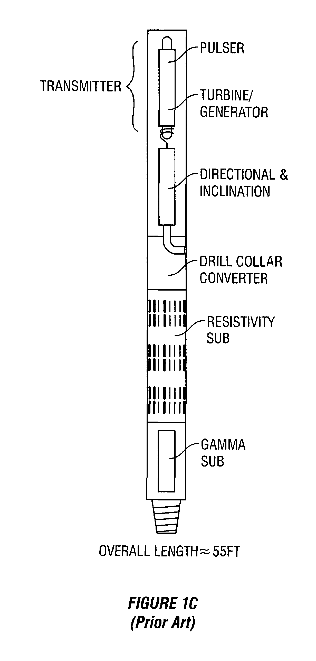
[0062]Wireline logging tools have been used successfully to produce subsurface images. Due to data bandwidth limitations related to conventional telemetry, for MWD or LWD applications, density tool measurements and other measurements have been stored in the MWD tool's memory. Therefore subsurface images and parameter determinations haven't been generally available for real time applications such as geosteering.

[0063]An LWD measurement data set can be used to create an image if the sensors are rotated during data acquisition, and the response (data) plotted versus well depth and azimuthal position around the bore. The result will be an image representation of the formation parameters particular to the sensors used.

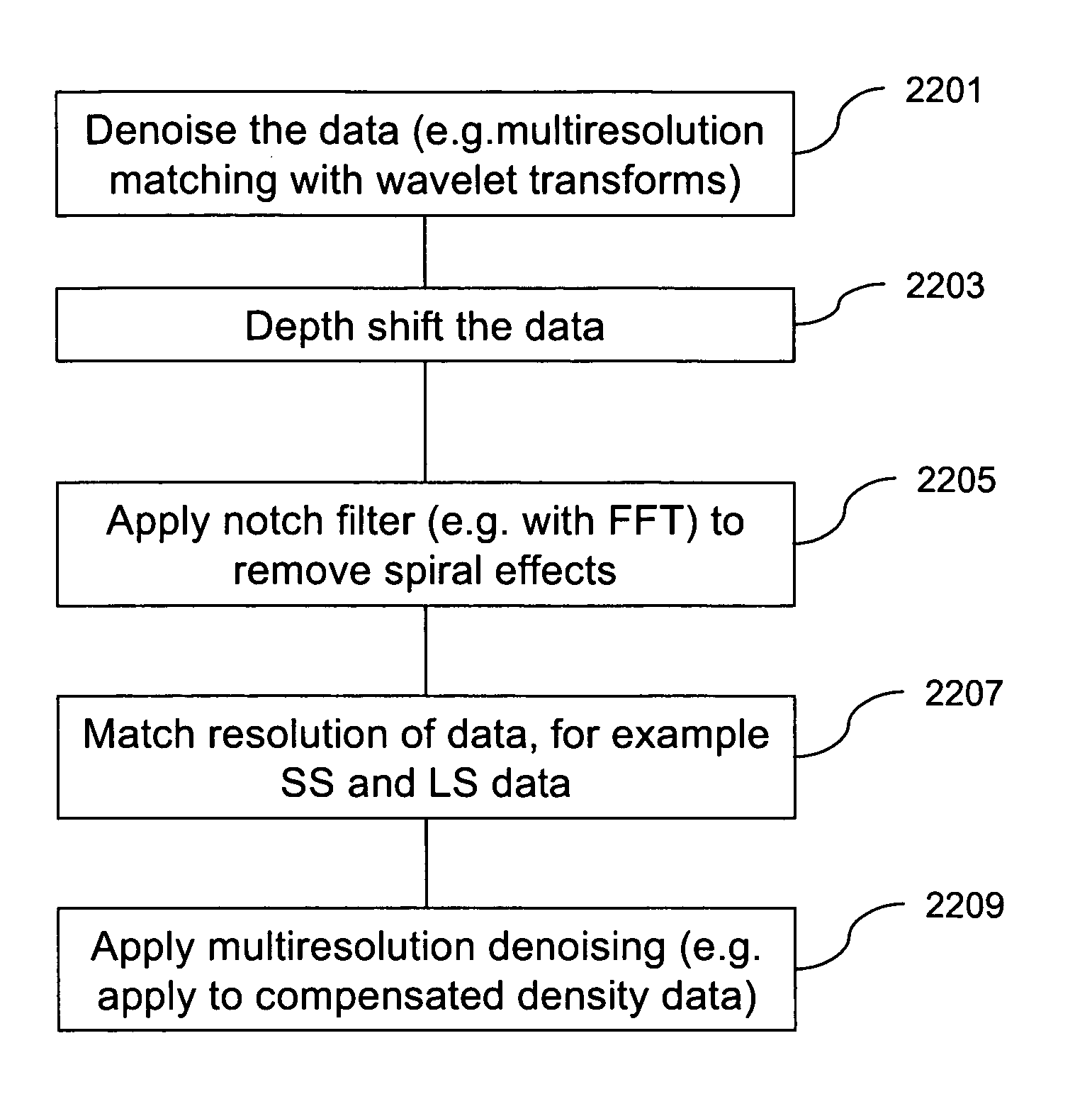
[0064]Processing techniques are applied to individual sensor responses, or the combined response function of a sensor array. These processing techniques when applied to the image improve the accuracy, enhance features, and remove false structure. Some examples of image arti...


PUM


Abstract

The present invention provides a method and apparatus for logging an earth formation and acquiring subsurface information wherein a logging tool is conveyed in a borehole to obtain parameters of interest. The parameters of interest obtained may be density, acoustic, magnetic or electrical values as known in the art. As necessary, azimuths associated with the measurements are obtained and corrections applied. The corrected data may be filtered and / or smoothed. The parameters of interest associated with azimuthal sectors are depth matched, resolution matched and filtered, and the acquisition effects removed. The data are denoised using a multi-resolution wavelet transform. The data acquired with separate transducers are resolution matched to obtain a resolution matched data series. Subsequently the resolution matched data may be further denoised using a multi-resolution wavelet transform.

Description

CROSS REFERENCES TO RELATED APPLICATIONS[0001]This application claims priority from U.S. Provisional Patent Application No. 60 / 620,903 filed on Oct. 21, 2004.FIELD OF THE INVENTION[0002]1. Field of the Invention[0003]This invention relates generally methods processing logging-while-drilling (LWD) measurements. More particularly, this invention relates to enhancing borehole images from logging data by removing acquisition artifacts.[0004]2. Background of the Art[0005]Oil well logging has been known for many years and provides an oil and gas well driller with information about the particular earth formation being drilled. In conventional oil well logging, after a well has been drilled, a probe known as a sonde is lowered into the borehole and used to determine some characteristic of the formations which the well has traversed. The probe is typically a hermetically sealed steel cylinder which hangs at the end of a long cable which gives mechanical support to the sonde and provides powe...

Claims


Application Information

Patent Timeline
Patent Type & Authority Patents(United States)
IPC IPC(8): G01V3/38
CPCG01V1/48G01V11/00G01V2210/6163G01V1/44G01V3/30G01V3/32G01V3/38G01V5/125
Inventor HASSAN, GAMALKIRKWOOD, ANDREWKURKOSKI, PHIL
Owner BAKER HUGHES INC
Why Eureka
Try Eureka