Optical transmitter

a technology of optical transmission line and optical transmission line, which is applied in the field of optical transmission line, can solve the problems of increasing the number of mz modulators, increasing the cost of analog electrical parts, and reducing the wavelength dispersion tolerance of optical transmission lines, so as to reduce the processing load of multi-level modulation processing

Active Publication Date: 2011-10-20
MITSUBISHI ELECTRIC CORP
View PDF17 Cites 25 Cited by
  • Summary
  • Abstract
  • Description
  • Claims
  • Application Information

AI Technical Summary

Benefits of technology

[0018]The optical transmitter according to the present invention includes a look-up table in which data for executing optical multi-level modulation is stored and from which first modulation data and second modulation data are output based on an input data series. This way, the first modulation data and the second modulation data are each output on a one-on-one basis with respect to the input data series.
[0019]The processing load of multi-level modulation processing can thus be lessened.

Problems solved by technology

When a symbol rate of symbols transmitted to an optical transmission line is increased without changing a modulation method, there is a problem in that wavelength dispersion tolerance of the optical transmission line reduces because an allowable residual dispersion amount is inversely proportional to the square of the symbol rate.
It is necessary to execute electrical signal processing at a high rate, and hence there is a problem in that the cost of an analog electrical part increases.
Even when any of the modulators as described in Patent Literature 1 and Non-Patent Literature 1 is used, the number of MZ modulators increases, and hence there is a problem in that a cost and the number of bias control points increase.

Method used


Image

  • Optical transmitter
  • Optical transmitter
  • Optical transmitter

Examples


first embodiment

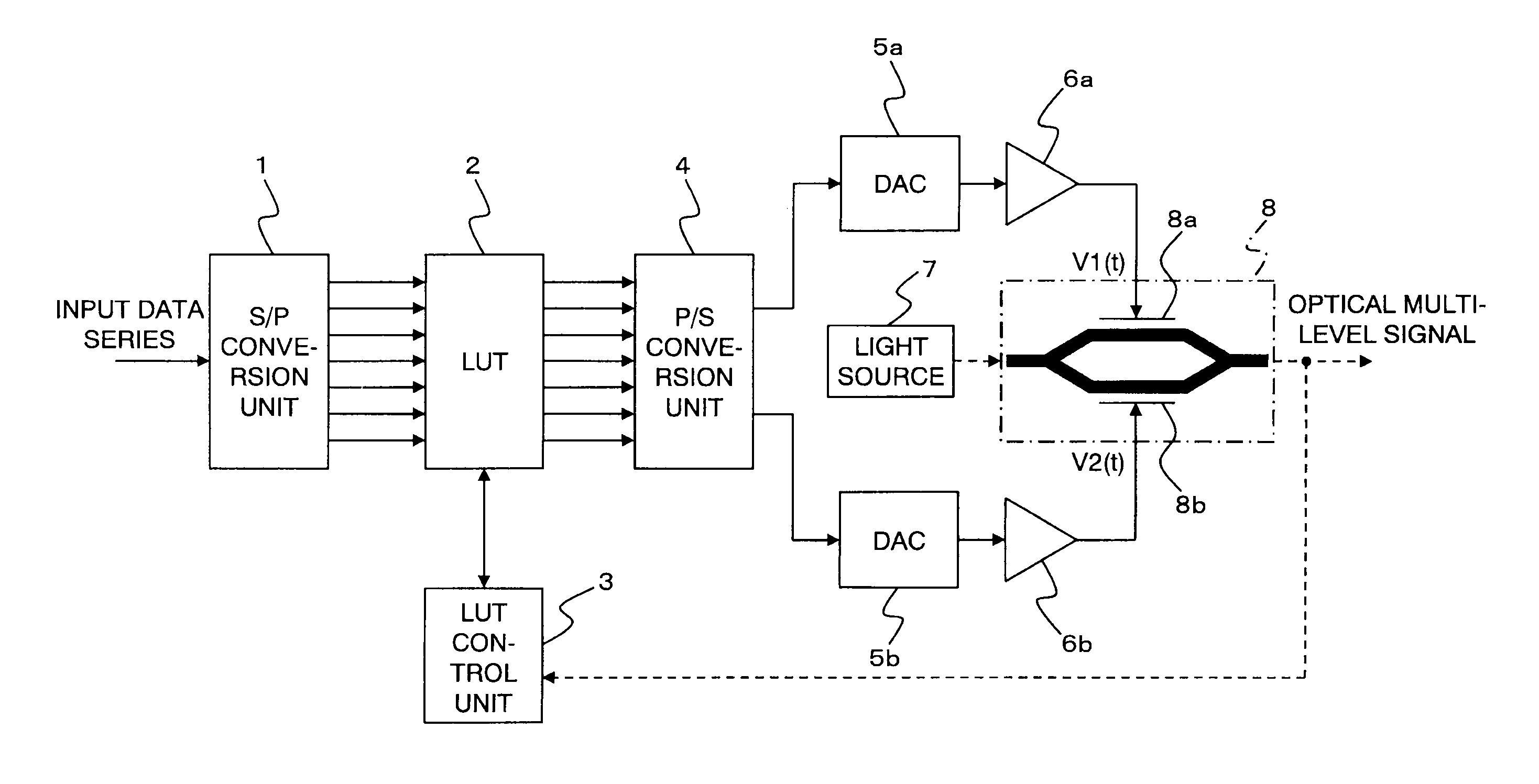
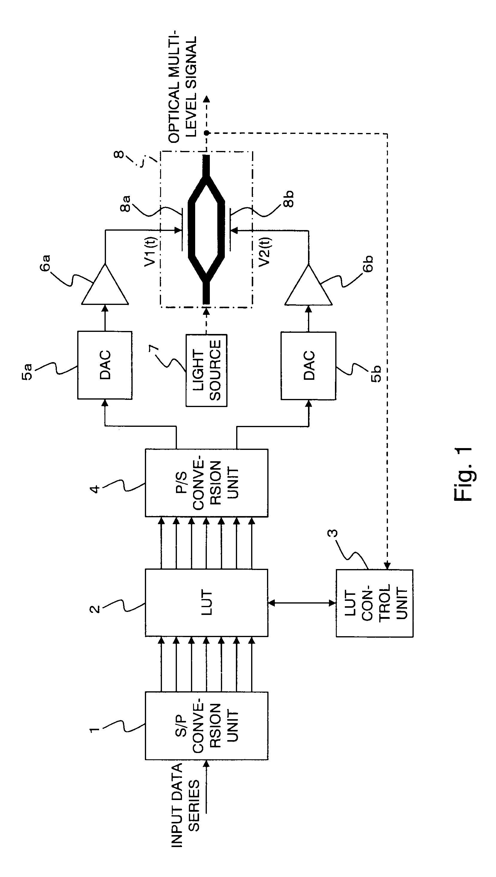
[0031]FIG. 1 is a block configuration diagram illustrating an optical transmitter according to a first embodiment of the present invention.

[0032]In FIG. 1, the optical transmitter includes the S / P (serial / parallel) conversion unit 1, the look-up table 2, a look-up table control unit 3, the P / S (parallel / serial) conversion unit 4, two D / A converters, 5a and 5b (a first D / A converter and a second D / A converter), two electrical amplifiers, 6a and 6b, a light source 7, and a dual-electrode MZ modulator 8.

[0033]The dual-electrode MZ modulator 8 is constituted of two phase modulators, 8a and 8b.

[0034]In the following description, the look-up table 2 is referred to as LUT 2. The D / A converters (digital / analog converters) 5a and 5b are referred to as DACs 5a and 5b.

[0035]Respective functions of the components of the optical transmitter are described below.

[0036]The S / P conversion unit 1 develops in parallel an input data series that has been input to the optical transmitter, in keeping wi...


PUM

PropertyMeasurementUnit
opticalaaaaaaaaaa
optical multi-levelaaaaaaaaaa
drive voltagesaaaaaaaaaa

Abstract

An optical transmitter for converting an input data series into an optical multi-level signal and for outputting the same, includes an LUT in which data for executing optical multi-level modulation is stored and from which first modulation data and second modulation data are output based on the input data series. A DAC converts the first modulation data by D / A conversion to generate a first multi-level signal. A DAC converts the second modulation data by D / A conversion to generate a second multi-level signal. A dual-electrode MZ modulator includes a first phase modulator for modulating light from a light source in accordance with the first multi-level signal and a second phase modulator for modulating light from the light source in accordance with the second multi-level signal, and combines an optical signal from the first phase modulator and an optical signal from the second phase modulator to output the optical multi-level signal.

Description

TECHNICAL FIELD[0001]The present invention relates to an optical transmitter for converting an electrical signal into an optical signal and transmitting the optical signal.BACKGROUND ART[0002]In order to realize a large capacity of a WDM optical communication system, it is useful to increase a transmission rate per wavelength. When a symbol rate of symbols transmitted to an optical transmission line is increased without changing a modulation method, there is a problem in that wavelength dispersion tolerance of the optical transmission line reduces because an allowable residual dispersion amount is inversely proportional to the square of the symbol rate. It is necessary to execute electrical signal processing at a high rate, and hence there is a problem in that the cost of an analog electrical part increases.[0003]Therefore, in recent years, researches for improving signal multiplicity per symbol without increasing the symbol rate so as to realize the large capacity of the system hav...

Claims


Application Information

Patent Timeline
Patent Type & Authority Applications(United States)
IPC IPC(8): H04B10/04H04B10/516G02F1/01H04B10/54H04B10/548H04B10/556H04B10/588H04B10/61
CPCH04B10/5053H04L27/36H04B10/516H04B10/5055
Inventor SUGIHARA, TAKASHIKAMETANI, SOICHIROMIZUOCHI, TAKASHIKONISHI, YOSHIAKI
Owner MITSUBISHI ELECTRIC CORP
Why Eureka
Try Eureka