Dome check valve

a check valve and dome technology, applied in the field of check valves, can solve the problems of difficult to achieve variability of valve characteristics, inability to check the flow of fluid, and metal presence in the i.v. line, and achieve the effect of high back pressure and highly economical valves

Active Publication Date: 2007-11-20
HALKEY ROBERTS CORP
View PDF19 Cites 40 Cited by
  • Summary
  • Abstract
  • Description
  • Claims
  • Application Information

AI Technical Summary

Benefits of technology

[0019]The valve element of the valve is self-supporting and when assembled in the valve, exerts a predetermined pressure against the valve seat thus sealing the valve. The element deflects at the center after pressure rises over the predetermined cracking pressure thus opening the flow path. The element deflection is directed by a concentric groove or grooves positioned on the inside of the element dome area. The dimensions of the groove(s) determine the valve opening pressure. The simple variation of groove dimensions thus achieves the goal of providing an economical way for valves to be manufactured at various preset cracking pressure conditions.
[0021]The valve has a relatively low, predetermined opening pressure one way and withstands relatively high back pressure in the opposite direction. Moreover, the valve housing is manufactured in a modular fashion, allowing the assembly of the same stem element into various housings having different connecting arrangements, such as ML, MLL, tubing fitment or barbed connector. The components of the envisioned new valve are producible reliably by high cavitation molds and are suitable for high speed assembly process, thereby resulting in a highly economical valve. None of the valve components require registration radially during assembly.

Problems solved by technology

In the opposite direction, however, the fluid pressure along with the spring forces the valve stem against a valve seat, thereby inhibiting, or checking the flow of fluid therethrough.
The presence of metal in an I.V. line presents possible contamination dangers from corrosion or metallic particles.
The variability of this valve characteristic is therefore not easily achieved.
Most valves that are designed to seal at low pressures, such as disc valves, do not normally allow for high flow or bi-directional flow.
Further, some valves with elastomeric elements where fluid flow is arranged to pass through the element itself have a possibility of particulate contamination.
These core features could be relatively easily damaged and could therefore cause flash and result in small particles of flash potentially breaking off and contaminating the fluid flow.

Method used


Image

  • Dome check valve
  • Dome check valve
  • Dome check valve

Examples


Embodiment Construction

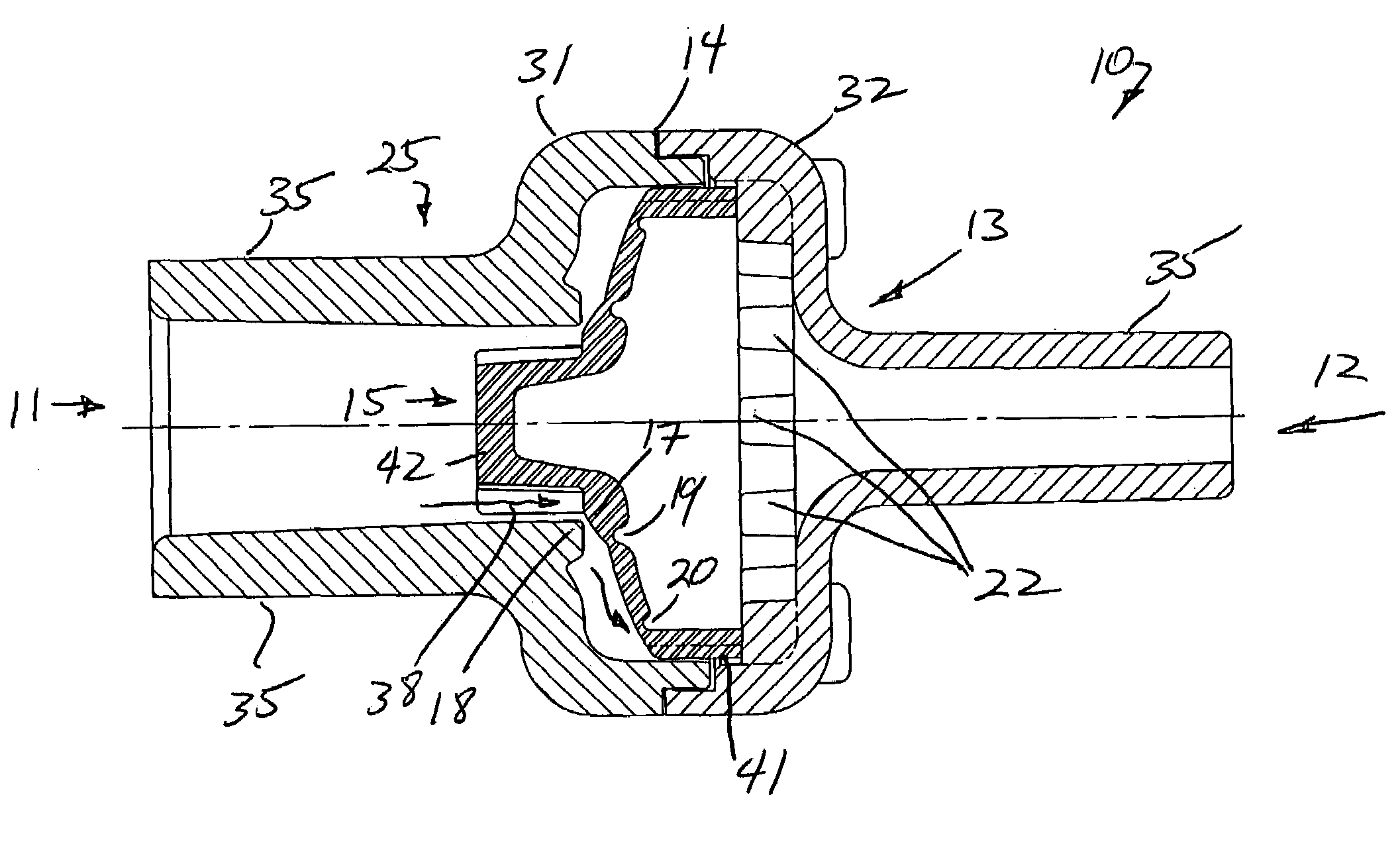
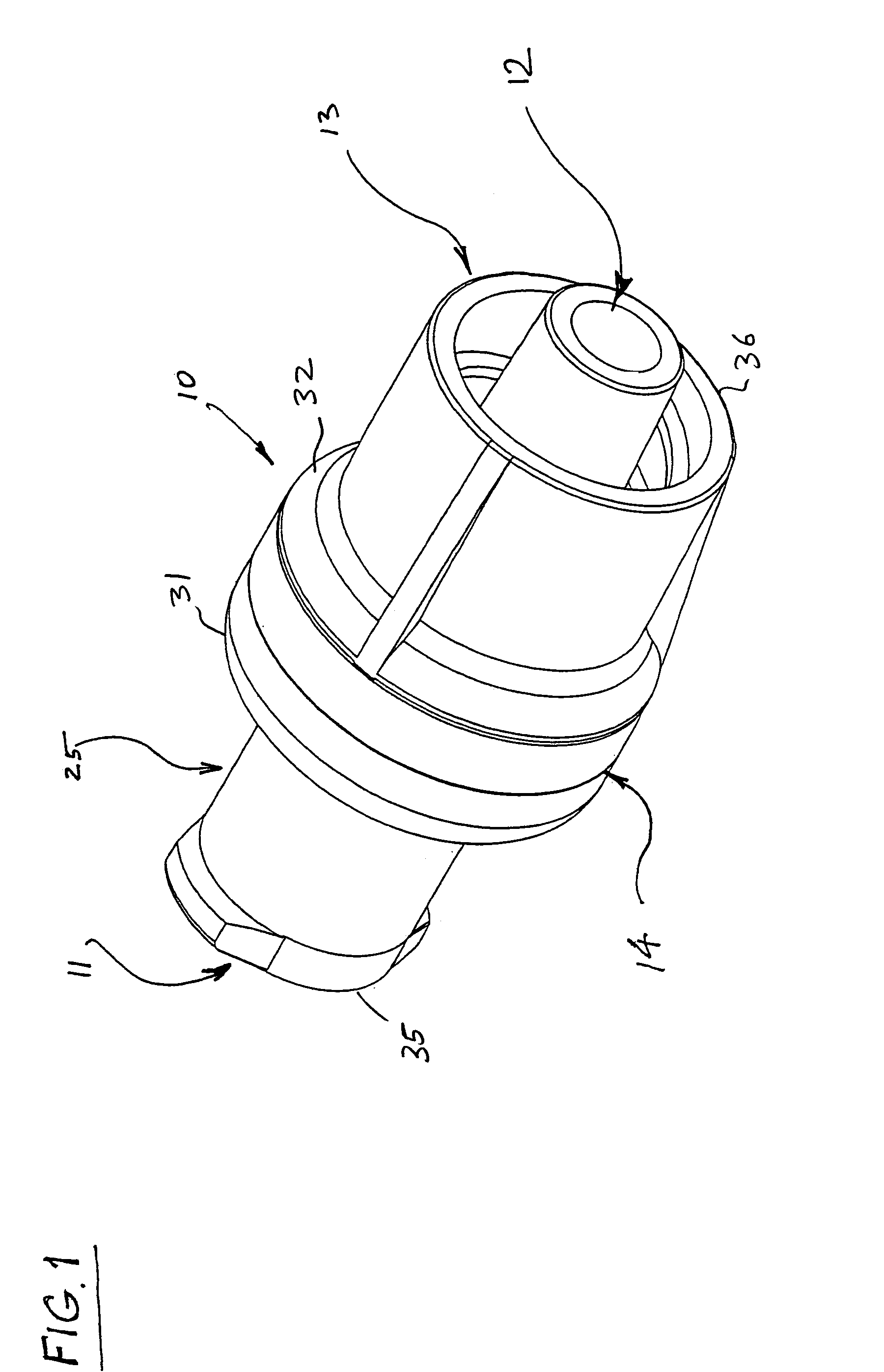
[0034]As best shown in FIGS. 1 and 8, the valve 10 of the invention comprises inlet housing 25 and an outlet housing 13 and an elastomeric valve element or stem 15. Housings 25 and 13 are permanently fastened together at joint 14 such as by welding or bonding.

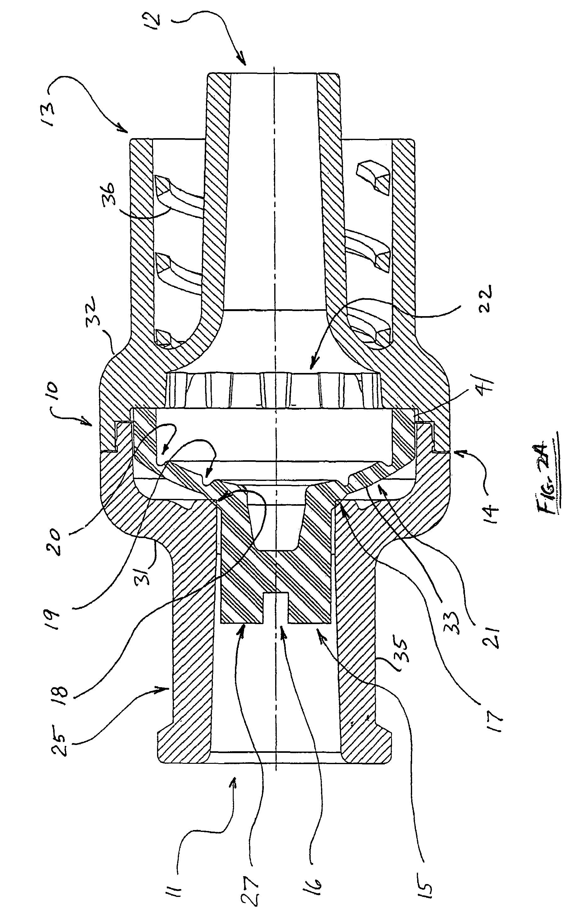
[0035]Referring to FIGS. 2A and 2B, the inlet housing 25 comprises a generally tubular configuration having a luer fitting 35 at its inlet 11 and a generally dome-shaped, larger diameter configuration 31 at its opposite end. Similarly, outlet housing 13 comprises a generally tubular configuration having a luer fitting 35 at its outlet 12 and a generally dome-shaped larger diameter configuration 32 at its opposite end which assembles with the dome-shaped end 31 of the inlet housing 25 at joint 14.

[0036]The inlet and outlet housings 25 and 13 may be provided with many types of fittings such as, in FIG. 8A, dual inlet and outlet barbed hose fittings 34, in FIG. 8B, inlet luer 35 and outlet hose barb fittings 34 (or vice versa), in...


PUM


Abstract

A valve comprising an inlet housing, an outlet housing, an elastomeric valve element having a generally dome-shaped configuration with a central integral stem positioned substantially concentrically therewith, the inlet housing and outlet housing being fastened together at a joint with the elastomeric valve element positioned therein and the valve element including a plurality of longitudinal ribs formed along an outer annular periphery of a lower end of the dome-shaped configuration that define flow channels that allow fluid flow from across an upper surface of the dome-shaped configuration through the flow channels.

Description

CROSS-REFERENCE TO RELATED APPLICATIONS[0001]This application claims the benefit of provisional application No. 60 / 615,479, filed Oct. 1, 2004, the disclosure of which is hereby incorporated by reference herein.BACKGROUND OF THE INVENTION[0002]1. Field of the Invention[0003]This invention relates to check valves, and relates more specifically to a check valve for needleless medical usage.[0004]2. Description of the Background Art[0005]Presently, there are many types of check valves which are designed to control the one-way flow of a fluid therethrough. One common type of check valve comprises a valve element, such as a ball or spring biased valve stem, reciprocatingly positioned within a valve body providing a fluid passageway. The flow of fluid in one direction through the valve body is permitted upon displacement of the stem as it flows around the valve stem to exit the valve body. In the opposite direction, however, the fluid pressure along with the spring forces the valve stem a...

Claims


Application Information

Patent Timeline
Patent Type & Authority Patents(United States)
IPC IPC(8): F16K51/00F16L29/00F16L37/28
CPCF16K15/141A61M39/26F16K15/144
Inventor ENERSON, JON R.JORDAN, GREGORY S.MILLER, PAVEL T.
Owner HALKEY ROBERTS CORP
Why Eureka
Try Eureka