Motor driving device and motor driving method

a technology of motor driving and driving method, which is applied in the direction of motor/generator/converter stopper, electronic commutator, dynamo-electric converter control, etc., can solve the problem of inability to detect the rotor position by the above method, the accuracy of finding the peak value of pulse current is not good, and the motor is not suitable for inexpensive motors. problems, to achieve the effect of improving the start speed, excellent response signal quality and low cos

Inactive Publication Date: 2007-11-20
COLLABO INNOVATIONS INC
View PDF29 Cites 23 Cited by
  • Summary
  • Abstract
  • Description
  • Claims
  • Application Information

AI Technical Summary

Benefits of technology

[0008]It is an object of the present invention to provide a motor driving device and a motor driving method in which a start period until a drive is switched from a start mode to a counter electromotive voltage feedback mode is shortened at low costs to improve a start speed.
[0076]According to the motor driving device and the motor driving method of the present invention, the response signal with respect to the applied rotor position search pulse is compared with the predetermined threshold value to determine the rotor position. In this case, there is a case where the rotor position can be immediately determined at a certain rate. Therefore, when the rotor position can be determined, the start rotation pulse current which starts the rotor can be immediately applied between the appropriate phase to be energized. Namely, according to the present invention, the start torque signal can be applied without a step of selecting all predetermined phases and then determining the rotor position. Therefore, the start period until the mode is switched from the start mode to the counter electromotive voltage feedback mode can be shortened and the start speed can be improved. In addition, since the response signal from the rotor position search pulse which is in a predetermined range is monitored, the quality of the response signal is excellent, so that the rotor position can be correctly determined. Furthermore, the above control can be implemented at low cost.

Problems solved by technology

However, since the counter electromotive voltage is not generated when the rotor is stopped, the rotor position cannot be detected by the above method when the rotor is stopped.
However, according to the method in the Japanese Patent Publication No. 2547778, there is a problem in accuracy in finding the peak value of the pulse current which flow when the rotor position search pulse is applied.
Therefore, the method is not suitable for an inexpensive motor in which characteristics with respect to each phase are not managed well.
Thus, in order to implement the above method, an arithmetic processing ability is needed, which is not suitable for a case where controllability by a motor only is required or a case of an inexpensive motor driving system.

Method used


Image

  • Motor driving device and motor driving method
  • Motor driving device and motor driving method
  • Motor driving device and motor driving method

Examples


first embodiment

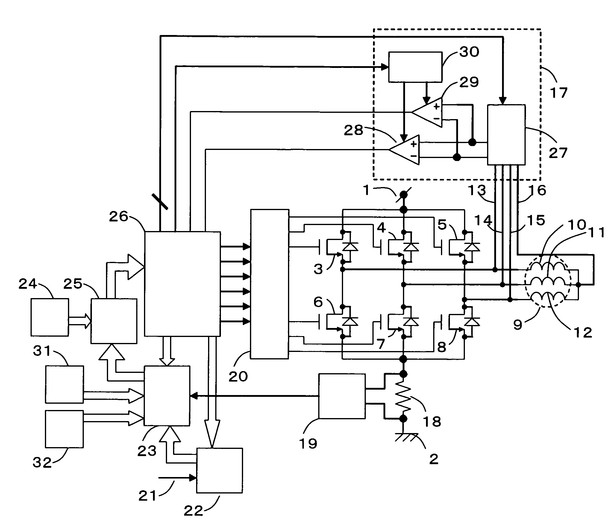
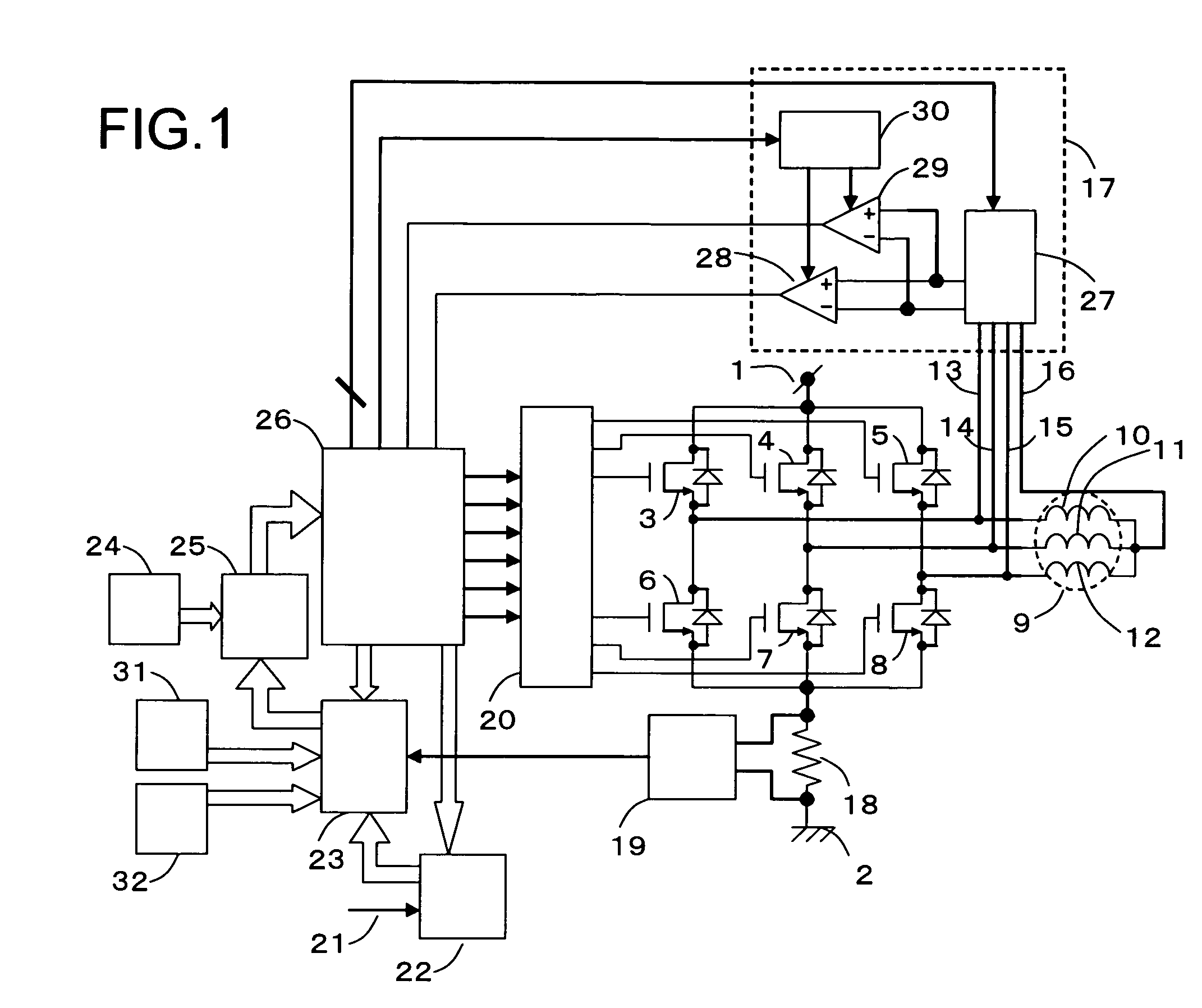
[0097]FIG. 1 is a block diagram showing a circuit constitution of a motor driving device according to first embodiment of the present invention. Referring to FIG. 1, the motor driving device includes a high-potential power line 1, a low-potential power line 2, a U-phase high-potential drive transistor 3, a V-phase high-potential drive transistor 4, a W-phase high-potential drive transistor 5, a U-phase low-potential drive transistor 6, a V-phase low-potential drive transistor 7, a W-phase low-potential drive transistor 8, a motor 9, a U-phase motor winding 10, a V-phase motor winding 11, a W-phase motor winding 12, a U-phase terminal line 13, a V-phase terminal line 14, a W-phase terminal line 15, a neutral point terminal line 16, a phase comparison control block 17, a current detection resistor 18, a current detection amplifier 19, a pre-driver 20, an external command signal 21, a component torque generation block 22, a torque comparison block 23, a PWM on-pulse generation block 24...

second embodiment

[0182]A motor driving method according to a second embodiment of the present invention is characterized in that it uses a response signal value provided by an inductive action when a current of a rotor position search pulse has a predetermined value. FIG. 5 is a view showing characteristics of a response signal generated between a W-phase terminal line 15 having a current of zero and a neutral point terminal line 16 with respect to the rotor position when a rotor position search pulse is applied from a U-phase winding terminal to a V-phase winding terminal in two cases having different current levels of the rotor position search pulse. Referring to FIG. 5, a curved line 51 designates the characteristics of the response signal when the rotor position search pulse current is high and the response signal characteristics 51 includes a main peak 52, a main bottom 53, a sub peak 54 and a sub bottom 55. In addition, a curved line 56 designates the characteristics of the response signal whe...

third embodiment

[0184]A motor driving method according to a third embodiment of the present invention is characterized in that a predetermined order is set when a current is applied from a certain phase winding to another phase winding, that is, when a certain combination of the two phases is selected with priority at the time of applying a rotor position search pulse. The phase windings to which the current is to be applied are determined by selecting the high-potential drive transistor and the low-potential drive transistor when the rotor position search pulse is applied. FIG. 7 shows electrical angular positions which can determine the rotor position when series windings of the two phases are selected from three phase windings and the rotor position search pulse is applied thereto.[0185](i) The rotor positions which can be detected by applying the rotor position search pulse current from a U-phase winding to V-phase winding are indicated in regions 71 and 72.[0186](ii) The rotor positions which ...


PUM


Abstract

A rotor position sensorless multiphase motor driving device includes a rotor; a plurality of phase windings; a common terminal to which one terminal of terminals at both ends of each winding is star connected; an upper-side drive transistor and a lower-side drive transistor connected to the other terminal of the winding; a commutation control unit operable to select two terminals other than the common terminal of the windings, and to turn on the corresponding pair of upper-side drive transistor and the lower-side drive transistor; a rotor position search pulse applying unit operable to apply a search pulse to the selected two terminals; and a comparing unit operable to detect a rotor position based on a response signal generated between the terminal which was unselected and the common terminal according to the search pulse application.

Description

[0001]This application is based on Japanese Patent Application No. 2005-211290 filed in Japan on Jul. 21, 2005, the contents of which are hereby incorporated by reference.BACKGROUND OF THE INVENTION[0002]1. Field of the Invention[0003]The present invention relates to a three-phase brushless motor driving device which can immediately and stably start without a rotor position sensor and a motor driving method at the time of start.[0004]2. Description of the Related Art[0005]According to a brushless motor, in order to apply a stable torque to a rotor by selecting an appropriate winding of a stator to apply a current thereto, information of a relative position of electrical angle of the rotor with respect to the stator is needed. Various kinds of rotor position sensors to find the relative position of the electrical angle of the rotor with respect to the stator are used. Meanwhile, a sensorless driving technique which does not need the rotor position sensor has been developed in view of...

Claims


Application Information

Patent Timeline
Patent Type & Authority Patents(United States)
IPC IPC(8): H02P25/12H02P6/18H02P6/06H02P6/08H02P6/182H02P21/04H02P21/18H02P21/24H02P21/34H02P23/03H02P27/06H02P27/08
CPCH02P6/182
Inventor YAMAMOTO, YASUNORIMORI, HIDEAKIKUROSHIMA, SHINICHIIGARASHI, YOSHIAKI
Owner COLLABO INNOVATIONS INC
Why Eureka
Try Eureka